USB full speed device interface (USB) UM0306
420/519
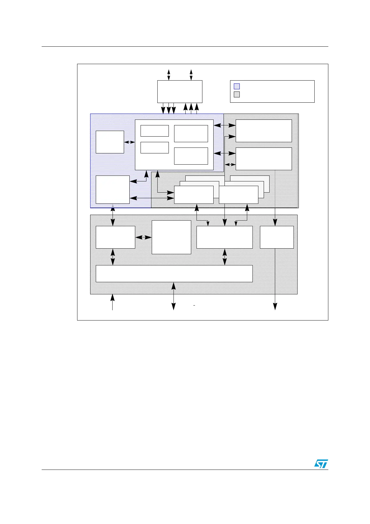
Figure 164. USB Peripheral block diagram
18.4 Functional description
The USB Peripheral provides an USB compliant connection between the host PC and the
function implemented by the microcontroller. Data transfer between the host PC and the
system memory occurs through a dedicated packet buffer memory accessed directly by the
USB Peripheral. The size of this dedicated buffer memory must be according to the number
of endpoints used and the maximum packet size. This dedicated memory is sized to 512
bytes and up to 8 mono-directional/single-buffered endpoints can be used. The USB
Peripheral interfaces with the USB host, detecting token packets, handling data
transmission/reception, and processing handshake packets as required by the USB
standard. Transaction formatting is performed by the hardware, including CRC generation
and checking.
Each endpoint is associated with a buffer description block indicating where the endpoint
related memory area is located, how large it is or how many bytes must be transmitted.
Arbiter
Packet
Buffer
Memory
Register
Mapper
Interrupt
Mapper
APB1 wrapper
Suspend
Timer
Packet
Buffer
Interface
USB
RX-TX
Clock
Recovery
Control
Endpoint
Selection
S.I.E.
Control
registers & logic
Interrupt
registers & logic
Analog
Endpoint
Registers
D+ D-
Transceiver
Endpoint
Registers
PCLK1 APB1 bus
IRQs to NVIC
USB Clock (48MHz)
PCLK1
APB1 Interface
 Loading...


