Inter-integrated circuit (I2C) interface UM0306
336/519
Closing the communication
After writing the last byte to the DR register, the STOP bit is set by software to generate a
Stop condition (see Figure 137 Transfer sequencing EV8_2). The interface goes
automatically back to slave mode (M/SL bit cleared).
Note: Stop condition should be programmed during EV8_2 event, when either TxE or BTF is set.
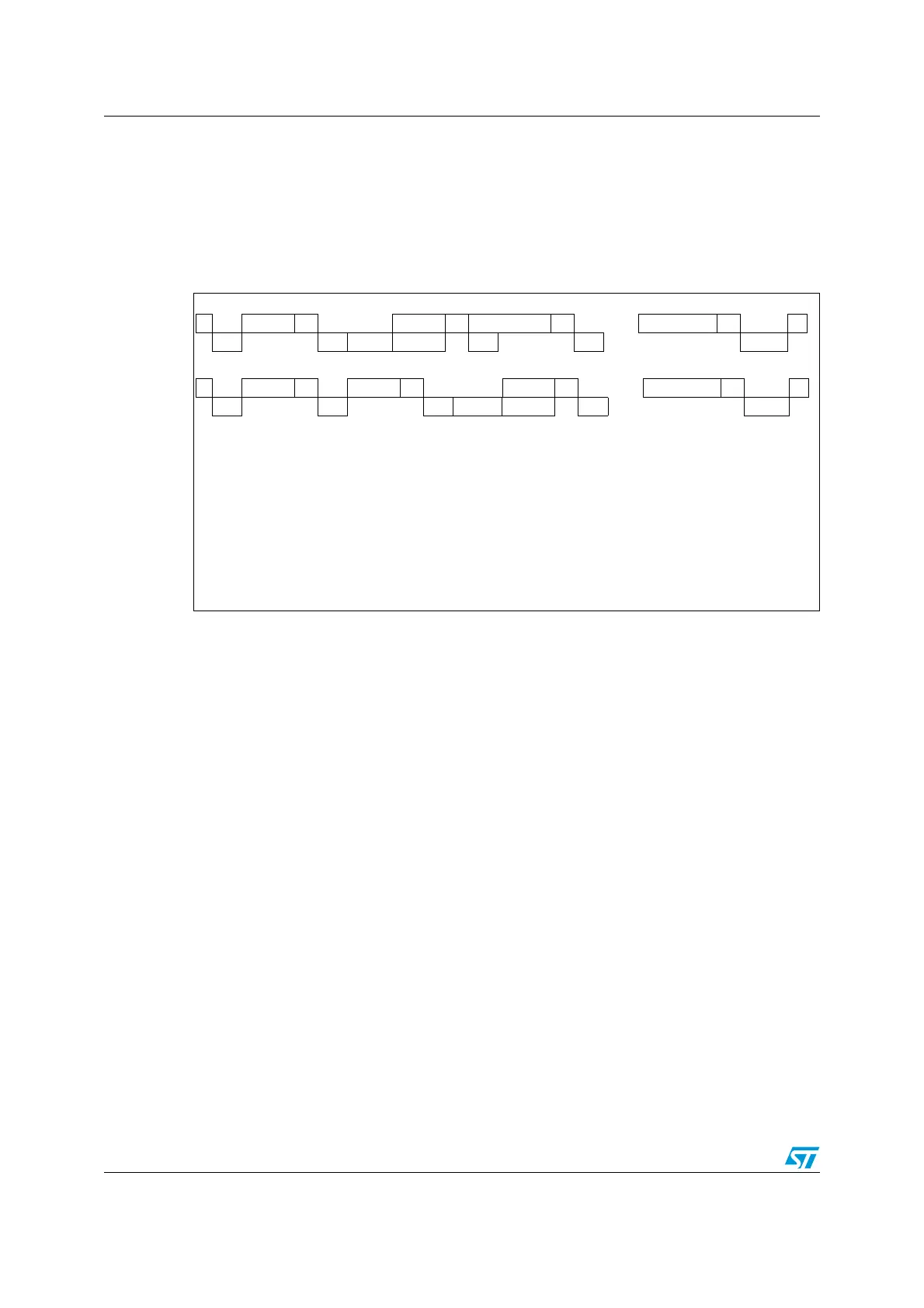
Figure 137. Transfer Sequence Diagram for Master Transmitter
7-bit Master Transmitter:
10-bit Master Transmitter
Legend: S= Start, S
r
= Repeated Start, P= Stop, A= Acknowledge, NA= Non-acknowledge,
EVx= Event (with interrupt if ITEVFEN=1)
EV5: SB=1, cleared by reading SR1 register followed by writing DR register with Address.
EV6: ADDR=1, cleared by reading SR1 register followed by reading SR2.
EV8_1: TxE=1 shift register empty
EV8: TxE=1 cleared by writing DR register.
EV8_2: TxE=1, BTF = 1 cleared by HW by stop condition
EV9: ADD10=1, cleared by reading SR1 register followed by writing DR register.
S Address A Data1 A Data2 A
.....
DataN A P
EV5 EV6 EV8_1 EV8 EV8 EV8 EV8_2
S Header A Address A Data1 A
.....
DataN A P
EV5 EV9 EV6 EV8_1 EV8 EV8 EV8_2
 Loading...


