Universal synchronous asynchronous receiver transmitter (USART) UM0306
406/519
17.4 USART register description
Refer to Section 1.1 on page 23 for a list of abbreviations used in register descriptions.
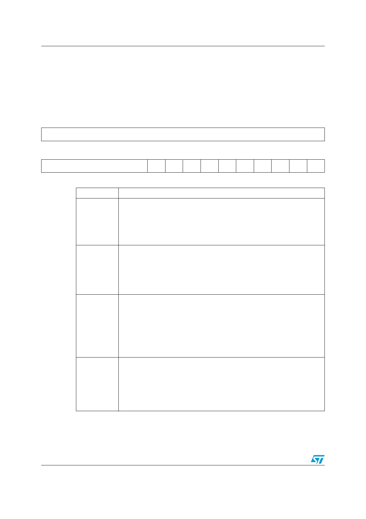
17.4.1 Status register (USART_SR)
Address Offset: 00h
Reset Value: 00C0h
31 30 29 28 27 26 25 24 23 22 21 20 19 18 17 16
Reserved
1514131211109876543210
Reserved CTS LBD TXE TC RXNE IDLE ORE NE FE PE
rcrcrrcrrrrrr
Bits 31:10 Reserved, forced by hardware to 0.
Bit 9
CTS: CTS Flag
This bit is set by hardware when the nCTS input toggles, if the CTSE bit is set. It
is cleared by software (by writing it to 0). An interrupt is generated if CTSIE=1 in
the USART_CR3 register.
0: No change occurred on the nCTS status line
1: A change occurred on the nCTS status line
Bit 8
LBD: LIN Break Detection Flag
LIN Break Detection Flag (Status flag)
0: LIN Break not detected
1: LIN break detected
Note:
An interrupt is generated when LBD=1 if LBDIE=1
Bit 7
TXE: Transmit Data Register Empty
This bit is set by hardware when the content of the TDR register has been
transferred into the shift register. An interrupt is generated if the TXEIE bit =1 in
the USART_CR1 register. It is cleared by a write to the USART_DR register.
0: Data is not transferred to the shift register
1: Data is transferred to the shift register)
Note:
This bit is used during single buffer transmission.
Bit 6
TC: Transmission Complete.
This bit is set by hardware when transmission of a frame containing Data is
complete. An interrupt is generated if TCIE=1 in the USART_CR1 register. It is
cleared by a software sequence (an read to the USART_SR register followed by
a write to the USART_DR register).
0: Transmission is not complete
1: Transmission is complete
 Loading...


