DMA controller (DMA) UM0306
114/519
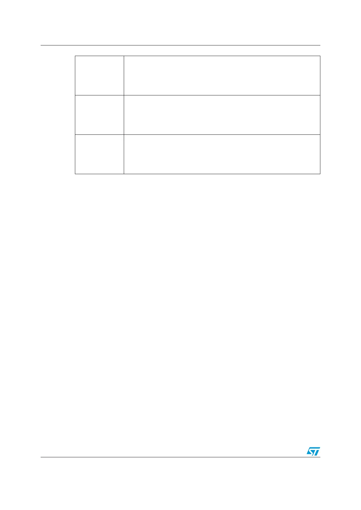
Bits 26, 22, 18,
14, 10, 6, 2
HTIFx: Channel x Half Transfer flag (x = 1 ..7)
This bit is set by hardware. It is cleared by software writing 1 to the
corresponding bit in the DMA_IFCR register.
0: No half transfer (HT) event on channel x
1: A half transfer (HT) event occurred on channel x
Bits 25, 21, 17,
13, 9, 5, 1
TCIFx: Channel x Transfer Complete flag (x = 1 ..7)
This bit is set by hardware. It is cleared by software writing 1 to the
corresponding bit in the DMA_IFCR register.
0: No transfer complete (TC) event on channel x
1: A transfer complete (TC) event occurred on channel x
Bits 24, 20, 16,
12, 8, 4, 0
GIFx: Channel x Global interrupt flag (x = 1 ..7)
This bit is set by hardware. It is cleared by software writing 1 to the
corresponding bit in the DMA_IFCR register.
0: No TE, HT or TC event on channel x
1: A TE, HT or TC event occurred on channel x
 Loading...


