Debug support (DBG) UM0306
500/519
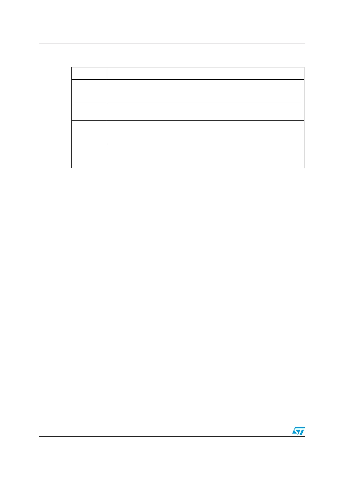
It consists of 4 registers:
Note: Important: these registers are not reset by a system reset. They are only reset by a power-
on reset.
Refer to the Cortex-M3 r1p1 TRM for further details.
To Halt on reset, it is necessary to:
● enable the bit0 (VC_CORRESET) of the Debug and Exception Monitor Control
Register
● enable the bit0 (C_DEBUGEN) of the Debug Halting Control and Status Register.
20.11 Capability of the debugger host to connect under system
reset
The STM32F10x MCU reset system comprises the following reset sources:
● POR (Power On Reset) which asserts a RESET at each power-up.
● Internal Watchdog Reset
● Software Reset
● External Reset
The Cortex-M3 differentiates the reset of the debug part (generally PORRESETn) and the
other one (SYSRESETn)
This way, it is possible for the debugger to connect under System Reset, programming the
Core Debug Registers to halt the core when fetching the reset vector. Then the host can
release the system reset and the core will immediately halt without having executed any
instructions. In addition, it is possible to program any debug features under System Reset.
Note: It is highly recommended for the debugger host to connect (set a breakpoint in the reset
vector) under system reset.
Register Description
DHCSR
The 32-bit Debug Halting Control and Status Register
This provides status information about the state of the processor enable core debug
halt and step the processor
DCRSR
The 17-bit Debug Core Register Selector Register:
This selects the processor register to transfer data to or from.
DCRDR
The 32-bit Debug Core Register Data Register:
This holds data for reading and writing registers to and from the processor selected
by the DCRSR (Selector) register.
DEMCR
The 32-bit Debug Exception and Monitor Control Register:
This provides Vector Catching and Debug Monitor Control. This register contains a
bit named TRCENA which enable the use of a TRACE.
 Loading...


