Configure
Left running head:
Chapter name (automatic)
44
Beta Beta
OmniAccess 5740 Unified Services Gateway Web GUI Users Guide
Alcatel-Lucent
• Enter the maximum receive unit (MRU) in the Slippage field in the range 16-
128.
MRU specifies the number of fragments that can be buffered per Virtual
Circuit. The default slippage MRU value is 32 MRU.
8. Configure the LMI (Local Management Interface) parameters in the LMI
Configuration table.
Configure the LMI values manually or click Set Defaults to set the default
values for LMI parameters.
• Select the LMI type from the LMI Type drop down list: Auto Sense/ANSI/
Q933A.
LMI Auto Sense is activated by default (as the system acts as a DTE).
The LMI Auto Sense will be activated when the physical interface is up
and LMI type is not configured on that interface.
• Enter the LMI Keep Alive interval in the Keep Alive field.
The default value is 10 seconds. The LMI keep alive value should
typically be equal to the corresponding interval at the switch.
• Enter the polling interval value in the Polling Interval field. The default value
is 6. This is used to set the full status polling interval on a DTE interface.
• Enter the DTE error threshold value in Error Threshold field. The default
value is 3.
• Enter the DTE monitored event count in the Monitored Event Count field.
The default value is 4.
9. FR can also be configured on a sub-interface. And, multiple sub-interfaces with
FR can be configured. For configuring Frame Relay on a sub-interface on a serial
interface, follow the steps given below:
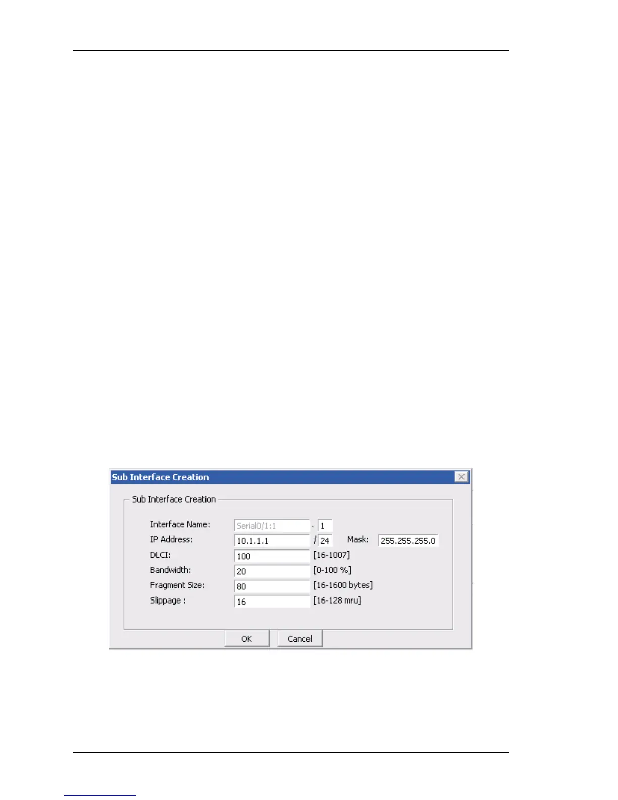
• Click Add Sub Interface to configure a sub interface. Sub Interface
Creation window is displayed.
Figure 22: Interfaces - Configure Frame Relay Encapsulation on a
Channelized Serial Interface - Add Sub Interface