394 Rockwell Automation Publication 2198-UM004A-EN-P - October 2019
Chapter 14 Absolute Position Recovery
Initializing Coordinates with Digital Input and Digital Output Signals
When the servo system is controlled by the host controller, you can reset the
absolute coordinate system with DI/DO signals. To initialize the coordinate
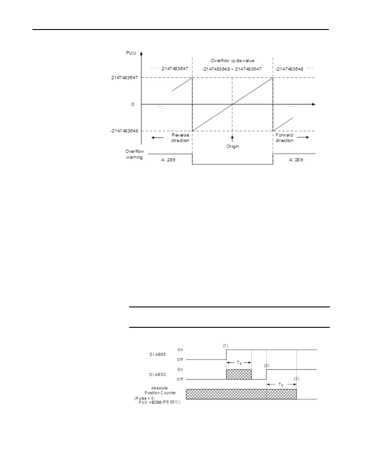
system, set the DI.ABSE signal to on and switch the DI.ABSC signal from off to
on. At that point, the pulse number is set to 0 and the PUU number is the value
of ID398 (P6.001) HomePosition. See to the following diagram for detailed
descriptions.
TIP After initializing the absolute coordinate system, any change to ID117
(P1.001.Z) or E-Gear ratio [ID151 (P1.044) and ID152 (P1.045)] changes the
original setting of the absolute coordinate system. If the parameters are
changed, reinitialize the coordinate system.
IMPORTANT (1), (2), and (3) represent the required delay time between triggering the
DI.ABSE and the DI.ABSC signals to enable the function.

 Loading...


