364 Rockwell Automation Publication 2198-UM004A-EN-P - October 2019
Chapter 12 Motion Control Applications
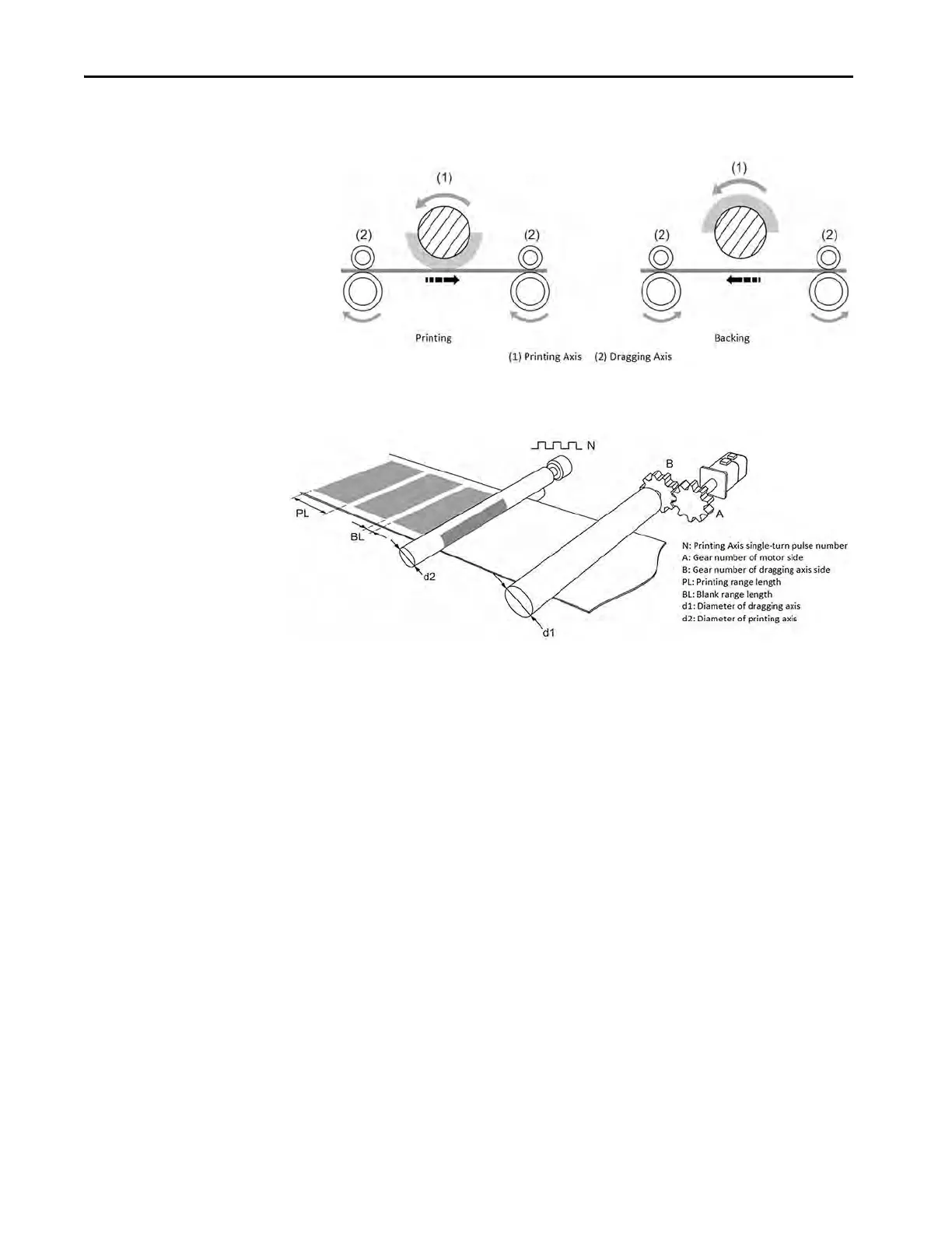
Figure 184 - Printing Machine Diagram
Figure 185 - Printing Machine Mechanical Structure
This type of E-Cam curve can be created by KNX5100C software.
1. To set the gear ratio, set the gear number (A) of the motor side and gear
number (B) of the dragging axis side.
2. To set PL and BL, set the length of printing range and blank range.
3. For d1, set the diameter of dragging axis.
4. For d2 and N, set the diameter of printing axis and its single-turn pulse
number.
5. Set the PUU numbers per revolution of the motor in one cycle by using
ID151 (P1.044) GearRatioFollowerCountsN1 and ID152 (P1.045)
GearRatioMasterCounts.
In this application, the ratio of the circumference length of the printing axis to
the length of the printing zone ( ) must be greater than 1
to save material.
The sync zone is obtained by software using the equation:

 Loading...


