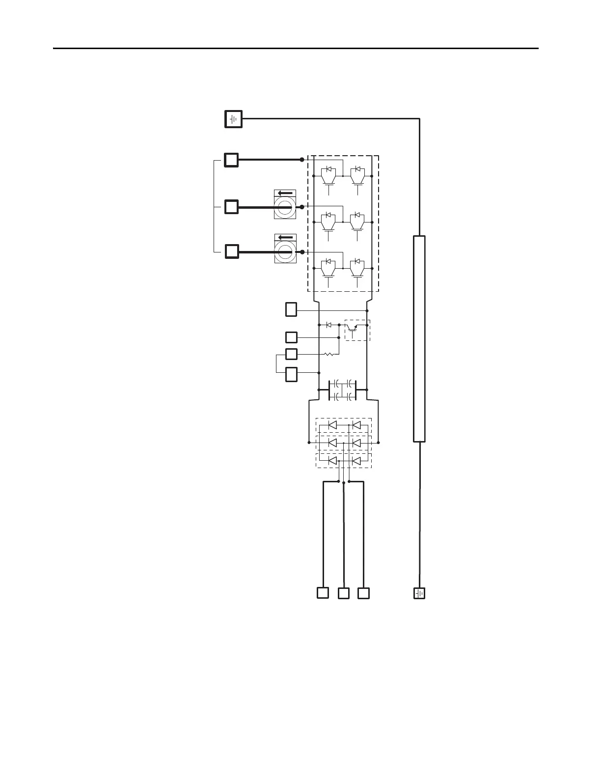
Only 2198-E1004-ERS, 2198-E1007-ERS,
2198-E1015-ERS, 2198-E1020-ERS, and
2198-E2030-ERS drives have internal shunt
and ISH terminal.
Chassis
Shunt/DC-bus Connector
Shunt
Transistor
Internal
Shunt
Resistor
Inverter Section
Three-phase Motor Output
Only 2198-E1004-ERS, 2198-E1007-ERS,
2198-E1015-ERS, and 2198-E1020-ERS drives
support both single-phase and three-phase operation.

 Loading...


