GE
P
ART NUMBER FN091065, REVISION 2 VS5 N AND VS6 N SERVICE MANUAL
8-34 Section 8-3 - Control Console Components Replacement Procedures
PRELIMINARY
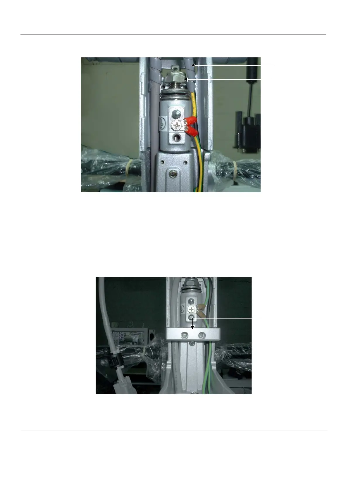
4.) Return the Locking Bolt to its location on the securing pin and turn it a few turns only - Figure 8-41.
5.) Replace cables in their position on either side of the upper support arm as shown in Figure 8-41.
6.) Position the grey spiral plastic shielding - coiling the shielding as shown in Figure 8-41. Start the
lower end of the spiral at the level of the washers on the support pin.
7.) Thread the cables through the aperture in the support arm in the following order:
- First, insert the black power cable
- Second, insert the DVI cable
8.) Return the cable holder bracket to its location on the upper arm - Figure 8-42.
Figure 8-41 Securing Locking Bolt on Upper Arm Securing Pin
Figure 8-42 Cable Holder Bracket
Locking Bolt
Plastic
Shielding
 Loading...


