GE
P
ART NUMBER FN091065, REVISION 2 VS5 N AND VS6 N SERVICE MANUAL
8-186 Section 8-6 - Lower Section Components Replacement Procedures
PRELIMINARY
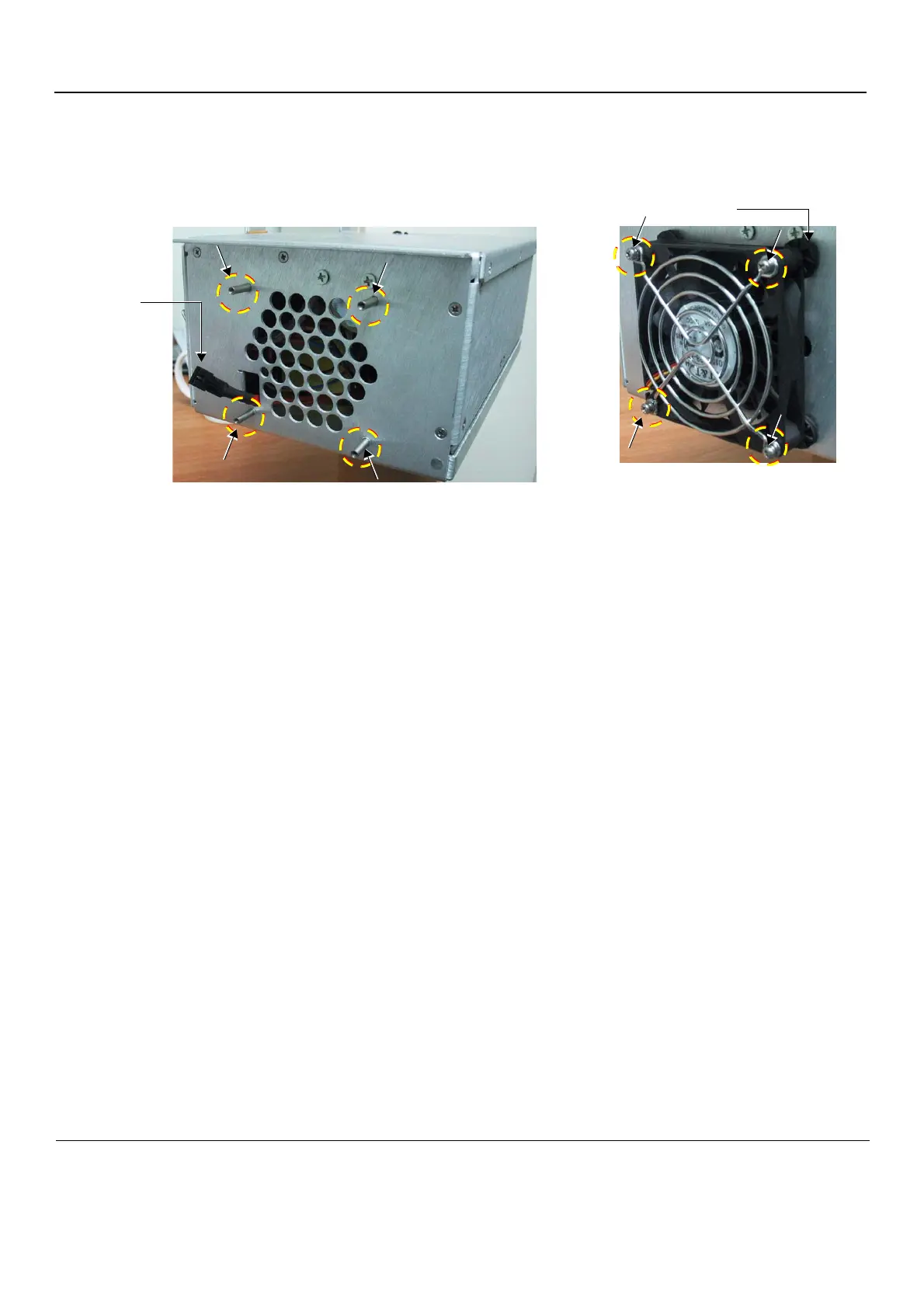
5.) Remove the Fan Assembly as follows:
a.) Unscrew the four retaining screws indicated in Figure 8-235.
b.) Remove the fan protecting grid and carefully pull the Fan Assembly away from the
AC Box chassis.
6.) Disconnect the fan’s electrical cable from the cable connector that protrudes from the AC Box (and
is attached to the cable inside the AC Box - shown in Figure 8-235).
Secure the AC Box cable firmly so that it cannot fall inside the AC Box housing.
Figure 8-235 AC Distribution Box showing Retaining Pins and Protecting Grid
Cable
Connector
(for Fan
Cable)
Rubber Bumper
 Loading...


