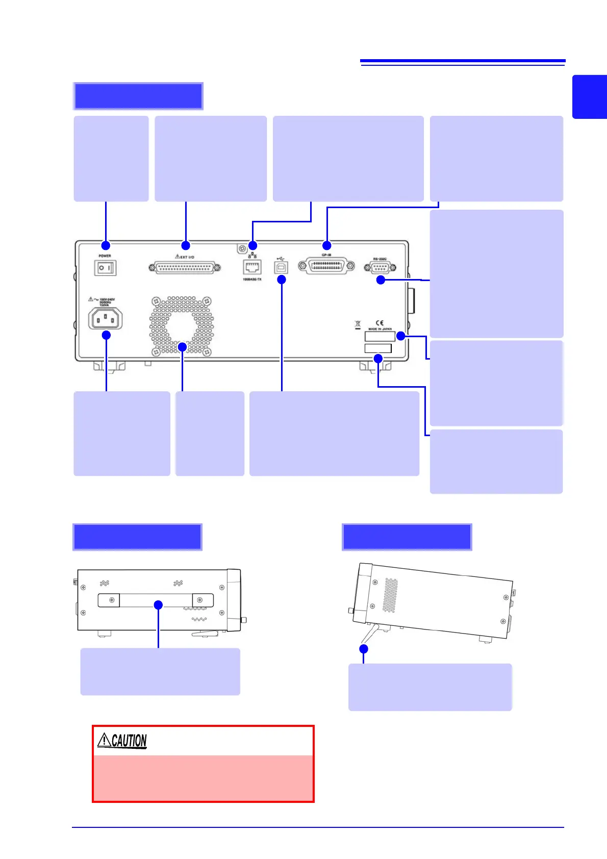
Rear
Main power
switch
Turns the power
on and off.
(p. 31)
EXT I/O Connector
Connect to a PLC or I/O
board to control measure-
ment start, and to acquire
comparator results
(p. 363)
Power Inlet
Connect the supplied
power cord.(p. 29)
Vent
Keep clear of
obstructions.
(p. 4)
GP-IB Connector
The GP-IB interface can be
used to connect to a computer
(Communication Instruction
Manual "Chapter 2” (CD))
LAN Connector
Connect to a computer to control
the instrument with communication
commands.
(Communication Instruction Manu-
al "Chapter 2” (CD))
USB Connector
Connect to a computer to control the
instrument with communication com-
mands.
(Communication Instruction Manual
"Chapter 2” (CD))
MAC address of the LAN
(p. 306)
(Communication Instruction
Manual "Chapter 2” (CD))
Manufacturer's Serial
Number
Shows the serial number.
Do not remove this label, as
it is required for product
support.
RS-232C Connector
The RS-232C interface can be
used to connect to a PLC or
computer.
(Communication Instruction
Manual "Chapter 2” (CD))
You can connect the IM3570
to an RS-232C printer in order
to print data. (p. 381)
Right side
• When using the stand
Extend the stand until it clicks into place.
Make sure to extend both legs of the stand.
•
Collapsing the stand
Fold in the stand until it clicks into place.
Stand
Enables the instrument to be tilted.
Left side
Handle
Use to carry the instrument.
Do not apply heavy downward pressure with
the stand extended. The stand could be dam-
aged.