14.3 Error display
408
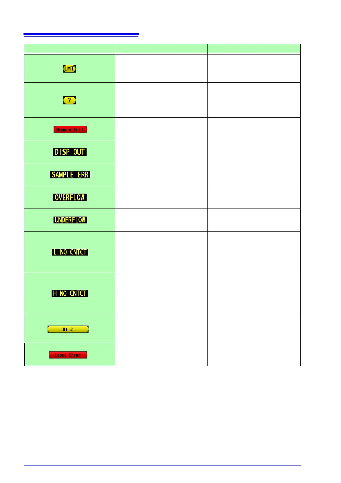
This is displayed when a signal level
that is lower than the set value is applied
to the test sample as a result of the volt-
age/current limit value setting.
Set the limit value again or change the
measurement signal level so that the
limit value is not exceeded. (p. 60)
This is displayed when load compensa-
tion is enabled and a load compensation
condition other than the frequency does
not match the current measurement
condition.
Match the current measurement condi-
tion to the load compensation condition.
(p. 288)
This is displayed when the measure-
ment results for the setting values are
stored in the memory of the instrument.
Load or clear them from the memory of
the instrument.(p. 219)
This is displayed when a measurement
value is outside of the screen display
range.
Change the measurement range to one
that matches the impedance of the ele-
ment to be measured. (p. 49)
This is displayed when measurement
does not end because of an internal cir-
cuit error.
The instrument needs to be repaired.
Contact your dealer or Hioki representa-
tive.
This is displayed when a measurement
value is at or above the upper limit value
of the auto ranging range.
Change the measurement range to a
high-impedance range. (p. 49)
This is displayed when a measurement
value is at or below the lower limit value
of the auto ranging range.
Change the measurement range to a
low-impedance range.(p. 49)
This is displayed when the terminal of
either L
POT
or L
CUR
is not connected be-
cause of, for example, a broken wire in
low impedance high accuracy mode.
• Check the connection of each termi-
nal. (p. 54)
• This may sometimes be displayed
when an element of other than a
capacitor is measured when using
DC bias. (p. 54)
This is displayed when the terminal of
either H
POT
or H
CUR
is not connected
because of, for example, a broken wire
in low impedance high accuracy mode.
• Check the connection of each termi-
nal. (p. 54)
• This may sometimes be displayed
when an element of other than a
capacitor is measured when using
DC bias. (p. 54)
This is displayed when a measurement
result is high in relation to the judgment
reference set for the HIGH-Z reject func-
tion.
Check the connection of each terminal.
(p. 108)
This is displayed when a detection level
error is detected while the detection lev-
el monitoring function is ON.
Check the connection of each terminal.
(p. 110)
Error display Description Remedy and Reference