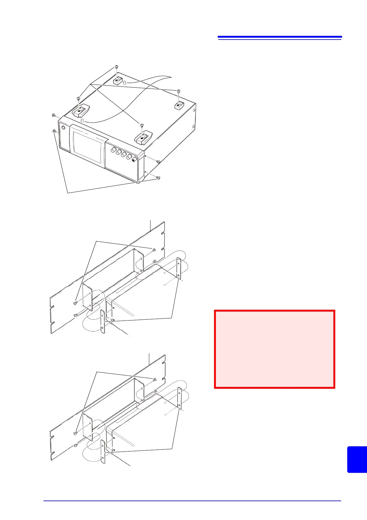
1. Remove the feed from the bottom of
the instrument, and the screws from
the sides (four near the front).
2. Installing the spacers on both sides
of the instrument, affix the Rack
Mounting Plate with the M4 x 12 mm
screws.
• When installing into the rack, reinforce
the installation with a commercially
available support stand.
• Please note that protrusions with a
diameter of 6 mm protrude from the
bottom of the instrument by 4 mm.For
details on the positions of the protru-
sions, refer to the external view on the
next page.
M4 x 6 mm
Spacers
Rack Mounting Plate (EIA)
Rack Mounting Plate (JIS)
Spacers
M4 x 12 mm
M3 x 6 mm
M4 x 12 mm
Installation Procedure
Protrusions