5
BRIDGE MODE SETTING SCREEN
5-54
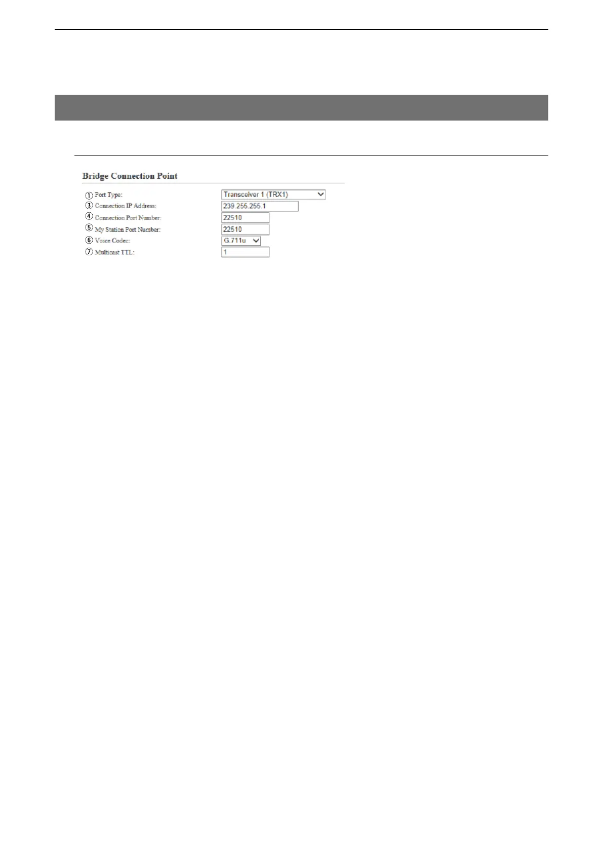
M Bridge Connection Point (continued)
7. [Bridge Connection] Menu
[Bridge Connection]–[Bridge Connection]
r Connection Port Number Enter the destination’s VE-PG3 port number.
(Enter the same port number as in the [My Station Port Number](t) item.)
• Setting range: Even numbers between 2 and 65534
(Some numbers may not be acceptable.)
• The set port number (RTP) and the port number +1 (RTCP) are used for the
communication.
• When using in the Unicast mode, do not set the port number which has
already been used by another connection setting.
• The default number differs, depending on the setting as shown below.
(Default: When [IP Communication Mode] is set to [Unicast]:
21500 (Transceiver 1 (TRX1)),
21502 (Transceiver 2 (TRX2)),
21504 (Digital Transceiver 1 (D-TRX1)),
21506 (Digital Transceiver 2 (D-TRX2)),
21508 (Digital Transceiver 3 (D-TRX3)),
21510 (Digital Transceiver 4 (D-TRX4)),
21512 (External Input1 (EXT1), External I/O 1 (EXT1)),
21514 (External Output1 (EXT1)),
21516 (External Input2 (EXT2), External I/O 2 (EXT2)),
21518 (External Output2 (EXT2)),
21540 (Controller 1),
21542 (Controller 2),
21544 (Controller 3),
21546 (Controller 4),
21520 (Emergency Notice),
When [IP Communication Mode] is set to [Multicast]:
22510 (Transceiver 1 (TRX1), Transceiver 2 (TRX2), Digital
Transceiver 1 (D-TRX1), Digital Transceiver 2 (D-TRX2), Digital
Transceiver 3 (D-TRX3), Digital Transceiver 4 (D-TRX4),
External Input1 (EXT1), External Output1 (EXT1), External I/O 1 (EXT1),
External Input2 (EXT2), External Output2 (EXT2), External I/O 2 (EXT2)),
Controller 1–Controller 4,
22520 (Emergency Notice).