6
CONVERTER MODE SETTING SCREEN
6-68
9. [Port Settings] Menu (continued)
M Transceiver 1 (TRX1)/Transceiver 2 (TRX2)
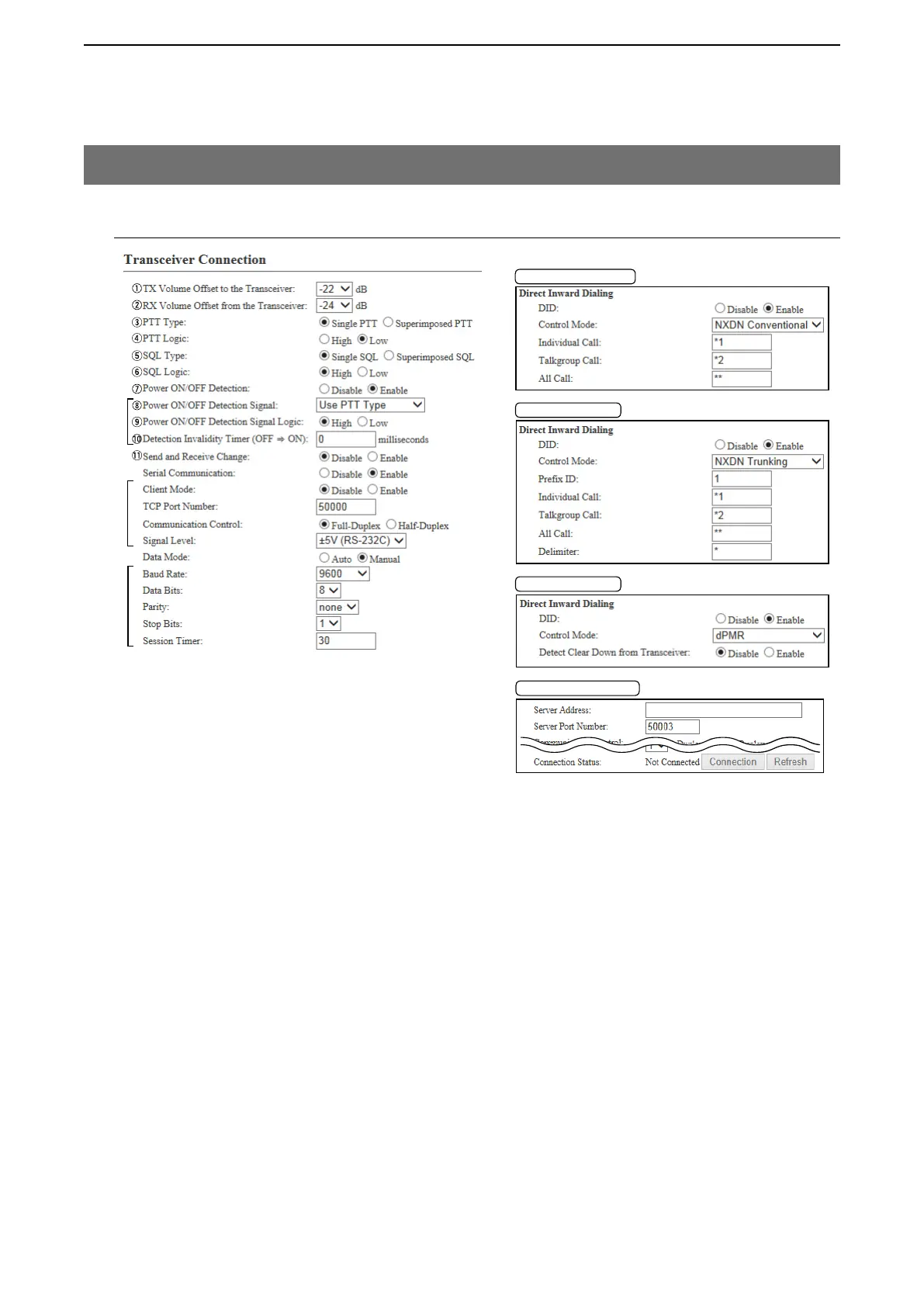
[Port Settings]–[Transceiver 1 (TRX1)/[Transceiver 2 (TRX2)]
!1 Send and Receive Change Select “Enable” to the commonly used line as the MIC input (A1 terminal)
and audio output (A3 terminal). (Default: Disable)
If your radio commonly uses one line as the MIC input and AF output, select
“Enable.”
!2 Serial Communication … … Select “Enable” to use the serial communication. (Default: Disable)
!3 Client Mode ……………… Select “Enable” to use the serial communication as the client.
(Default: Disable)
!4 TCP Port Number ……… Enter the port number between 1024 and 65535. (Default: TRX1 50000,
TRX2 50001
)
!5 Communication Control … Select the communication type. (Default: Full-Duplex)
!6 Signal Level ……………… Select the serial communication line signal level from “±5 V (RS-232C),”
“0V/5V (Logic)” and “0V/3V (Logic).” (Default: ±5 V (RS-232C))
*
1
Appears only when “Enable” is selected in [Power Detection].
*
2
Appears only when “Enable” is selected in [Serial Communication].
*
3
Appears only when “Manual” is selected in [Data Mode].
*
1
*
2
*
3
!2
!3
!4
!5
!6
!7
!8
!9
@0
@1
@2
@3
@3
@3
@4
@4
@4
@5
@5
@6
@6
@7
@8
@8
@9
#0
"NXDN Trunking"
"NXDN Conventional"
"dPMR"
Client Mode:Enable
#1
#2
#3