Datasheet 687
Integrated Intel
®
High Definition Audio Controller Registers
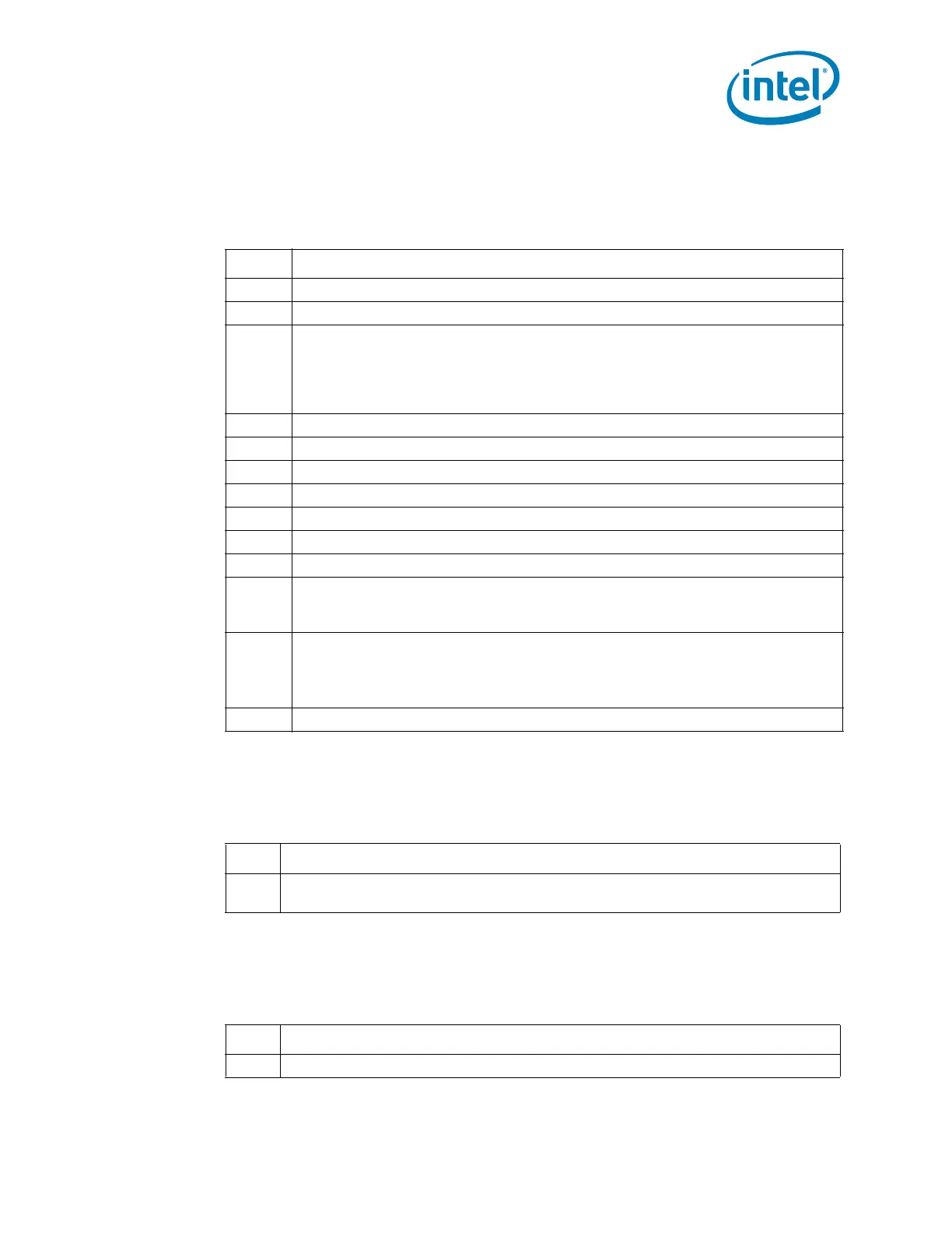
17.1.1.4 PCISTS—PCI Status Register
(Intel
®
High Definition Audio Controller—D27:F0)
Offset Address: 06h–07h Attribute: RO, R/WC
Default Value: 0010h Size: 16 bits
17.1.1.5 RID—Revision Identification Register
(Intel
®
High Definition Audio Controller—D27:F0)
Offset: 08h Attribute: RO
Default Value: See bit description Size: 8 Bits
17.1.1.6 PI—Programming Interface Register
(Intel
®
High Definition Audio Controller—D27:F0)
Offset: 09h Attribute: RO
Default Value: 00h Size: 8 bits
Bit Description
15 Detected Parity Error (DPE) — RO. Not implemented. Hardwired to 0.
14 SERR# Status (SERRS) — RO. Not implemented. Hardwired to 0.
13
Received Master Abort (RMA) — R/WC. Software clears this bit by writing a 1 to it.
0 = No master abort received.
1 = The Intel
®
High Definition Audio controller sets this bit when, as a bus master, it
receives a master abort. When set, the Intel
®
High Definition Audio controller
clears the run bit for the channel that received the abort.
12 Received Target Abort (RTA) — RO. Not implemented. Hardwired to 0.
11 Signaled Target Abort (STA) — RO. Not implemented. Hardwired to 0.
10:9 DEVSEL# Timing Status (DEV_STS) — RO. Does not apply. Hardwired to 0.
8 Data Parity Error Detected (DPED) — RO. Not implemented. Hardwired to 0.
7 Fast Back to Back Capable (FB2BC) — RO. Does not apply. Hardwired to 0.
6 Reserved.
5 66 MHz Capable (66MHZ_CAP) — RO. Does not apply. Hardwired to 0.
4
Capabilities List (CAP_LIST) — RO. Hardwired to 1. Indicates that the controller
contains a capabilities pointer list. The first item is pointed to by looking at
configuration offset 34h.
3
Interrupt Status (IS) — RO.
0 = This bit is 0 after the interrupt is cleared.
1 = This bit is 1 when the INTx# is asserted.
Note that this bit is not set by an MSI.
2:0 Reserved.
Bit Description
7:0
Revision ID — RO. See the Intel
®
6 Series Chipset Specification Update for the value
of the RID Register.
Bit Description
7:0 Programming Interface — RO.
 Loading...