REV 0, June 2005Page 100
Operation Manual SUPREMA
5. Installation
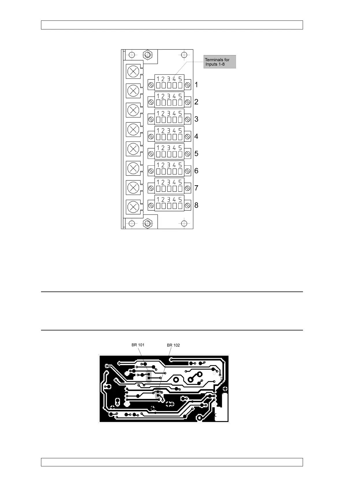
Figure 5-5: MCI 10 module, solder bridges
Figure 5-4: MAT module, position of the terminals for input 1–8
5.3.3 Configuration of MCI 10/MCI 20/MCI 20 BFE Module (active sensors)
The MCI 10 module can be configured for various types of active sensors by the use of solder
bridges.
Note: Any type of sensor or device which has a 4 ... 20 mA output, a 0 ... 24 V
output, or a volt-free contact output can be connected. To connect sensors not
from MSA, however, you must discuss this with your MSA technical contact
person to avoid problems.