REV 0, June 2005Page 126
Operation Manual SUPREMA
5. Installation
Connection Note:
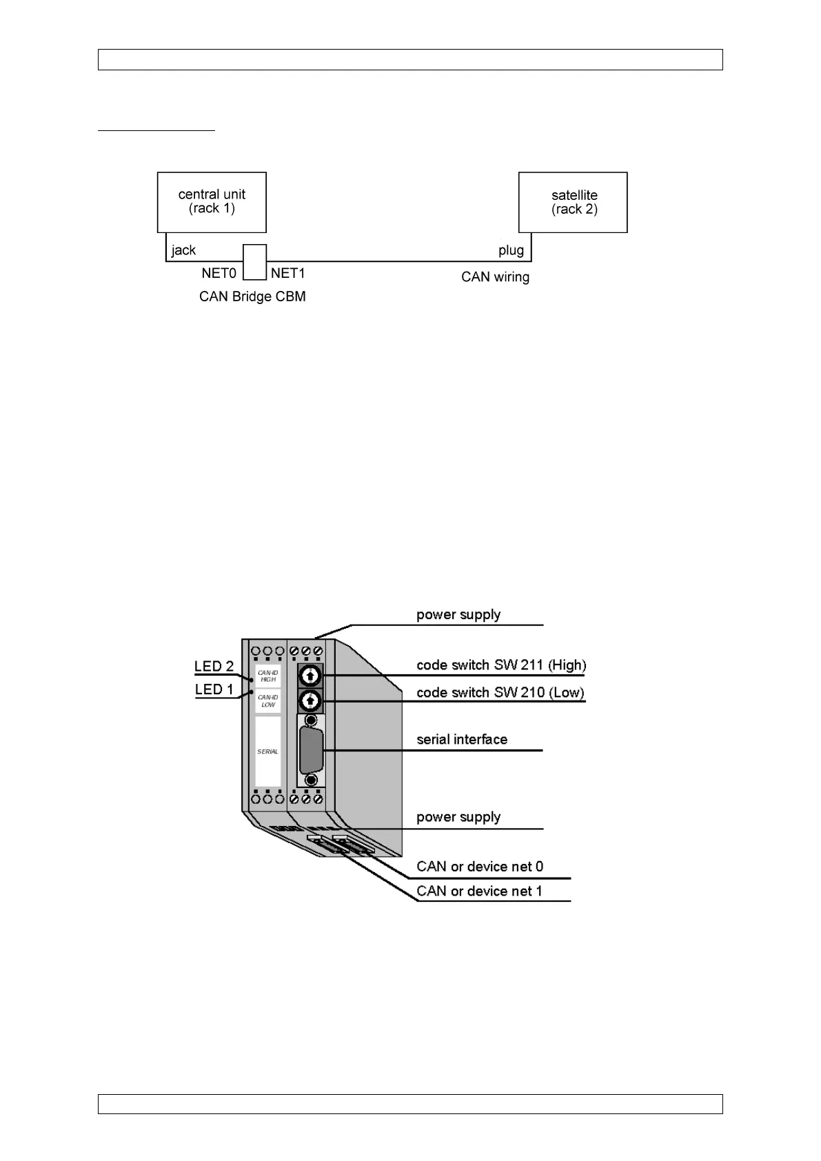
Figure 5-28: Connection CAN-Bridge CBM
The terminating resistor of rack 1 must be deactivated, and a 120 Ohm resistor connected
between terminal 2 and 4, NET 0, of the CAN connection.
A 120 ohms resistor for Net 1 must be connected under the terminal (2 to 4) NET1 of the CAN
connection.
5.5.2.1 SUPREMA CAN-Bridge CBM
If a satellite is operated with a cable length > 20 metres, a SUPREMA CAN BRIDGE CBM must
be provided. It is necessary for galvanic isolation, the matching of bit rates and the filtering of
CAN Identifiers (data reduction).
Figure 5-29: SUPREMA CAN-Bridge CBM
The SUPREMA CAN BRIDGE is supplied with 24V DC (X101). The CAN Bus of the Basic Rack
is connected to NET 0 (X400), and the satellite rack is connected to NET1 (X400) (Exact
connection assignments are to be seen from the CAN Bridge hardware).