REV 0, June 2005Page 102
Operation Manual SUPREMA
5. Installation
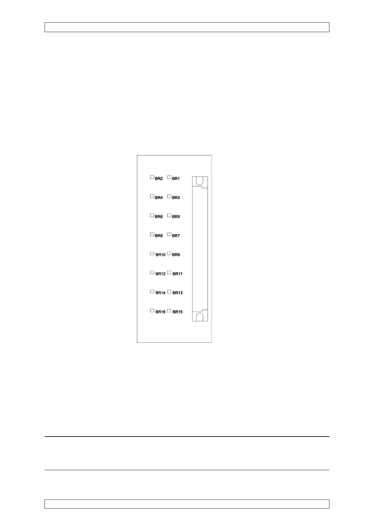
Assignment: BR1, BR2 ⇒ input 1
BR3, BR4 ⇒ input 2
BR5, BR6 ⇒ input 3
BR7, BR8 ⇒ input 4
BR9, BR10 ⇒ input 5
BR11, BR12 ⇒ input 6
BR13, BR14 ⇒ input 7
BR15, BR16 ⇒ input 8
Figure 5-6: Configuration of MAT module
5.3.5 Configuration of MAT-TS Module
On top of the circuit board, next to the ribbon cable plug, 2 solder bridges for each input are
provided for the 3 or 5 wire operation of the sensors:
Solder bridge OPEN = 5 wire operation
Solder bridge CLOSED = 3 wire operation
Note: The solder bridges for 3 wire operation should be closed only when passi-
ve sensors (MPI module) are connected. For 5 wire operation with active sensors
(MCI module), the solder bridges must be open!