REV 0, June 2005Page 170
Operation Manual SUPREMA
6. Startup
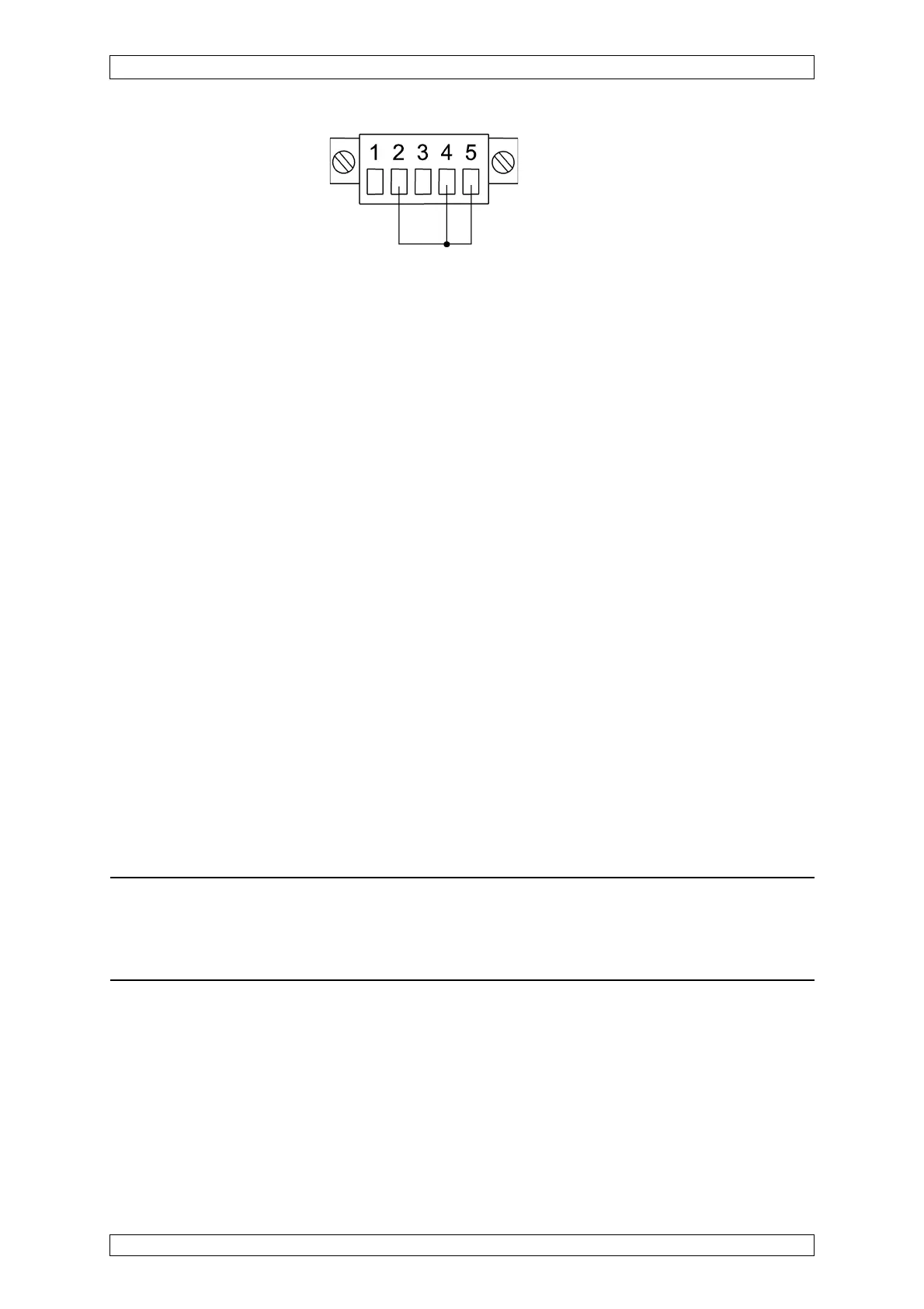
Figure 6-10: Equivalent sensor circuit for the MPI-HL8101/MPI-HL8113 module
• Connect the equivalent sensor circuit to the inputs to be adjusted.
• Connect the digital multimeter to the test sockets on the MAI module (red/black) and
select the 3 VDC measuring range.
• Enable operator buttons (UP, DOWN, MS) by pressing the SEL-Button.
• Select the input by pressing the MS button; each press of the button advances the
selection by one input. The selected site is indicated by the front row of LEDs (LED at
the top = input 1, LED at the bottom = input 8). The LED of the selected input lights up
green.
• Using the SEL button, select the function IBR (bridge current) (LED IBR lights up red).
• By pressing the UP or the DOWN button, adjust the bridge current specified for the
sensor (± 1 %) (see the sensor data sheet or the sensor O&M instructions). Note: The
voltage in mV present at the test sockets corresponds to the adjusted current in mA
(e.g., 270 mV = 270 mA)
Repeat these steps for each of the passive sensors to be connected.
Disable operator keys by pressing the SEL-Button until the INPUT LED go out.
Then remove the short-circuit bridge (terminal 2/terminal 4), and connect the sensor cable.
After the sensors are connected, it is recommended that the bridge current for each individual
sensor be checked again and corrected if necessary.
6.3.3.2 Preadjust the Zero Point/Sensitivity
After the sensors have been allowed to stabilise for a sufficient period of time – which depends
on the types of sensors and measuring components (see the associated sensor O&M
instructions) – a preliminary adjustment must be performed on the MAI module with gas.
Note: To perform the preliminary adjustment, at least 2 people are required. To
avoid communication problems between person 1 operating the SUPREMA and
Person 2 supplying the sensors with gas, we recommend the use of a set of
appropriate two-way radios.
In addition, the required zero and test gases as well as test adapters and hose connections
(see sensor O & M instructions) for supplying the gases are a necessary precondition for the
successful completion of the preliminary adjustment with gas.
The flow rate and the duration of the test gas supply can be found in the associated sensor
operating and maintenance instructions.
For the preliminary adjustment, person 1 (at the SUPREMA) and person 2 (at the sensor in
question) must perform the following steps: