REV 0, June 2005Page 108
Operation Manual SUPREMA
5. Installation
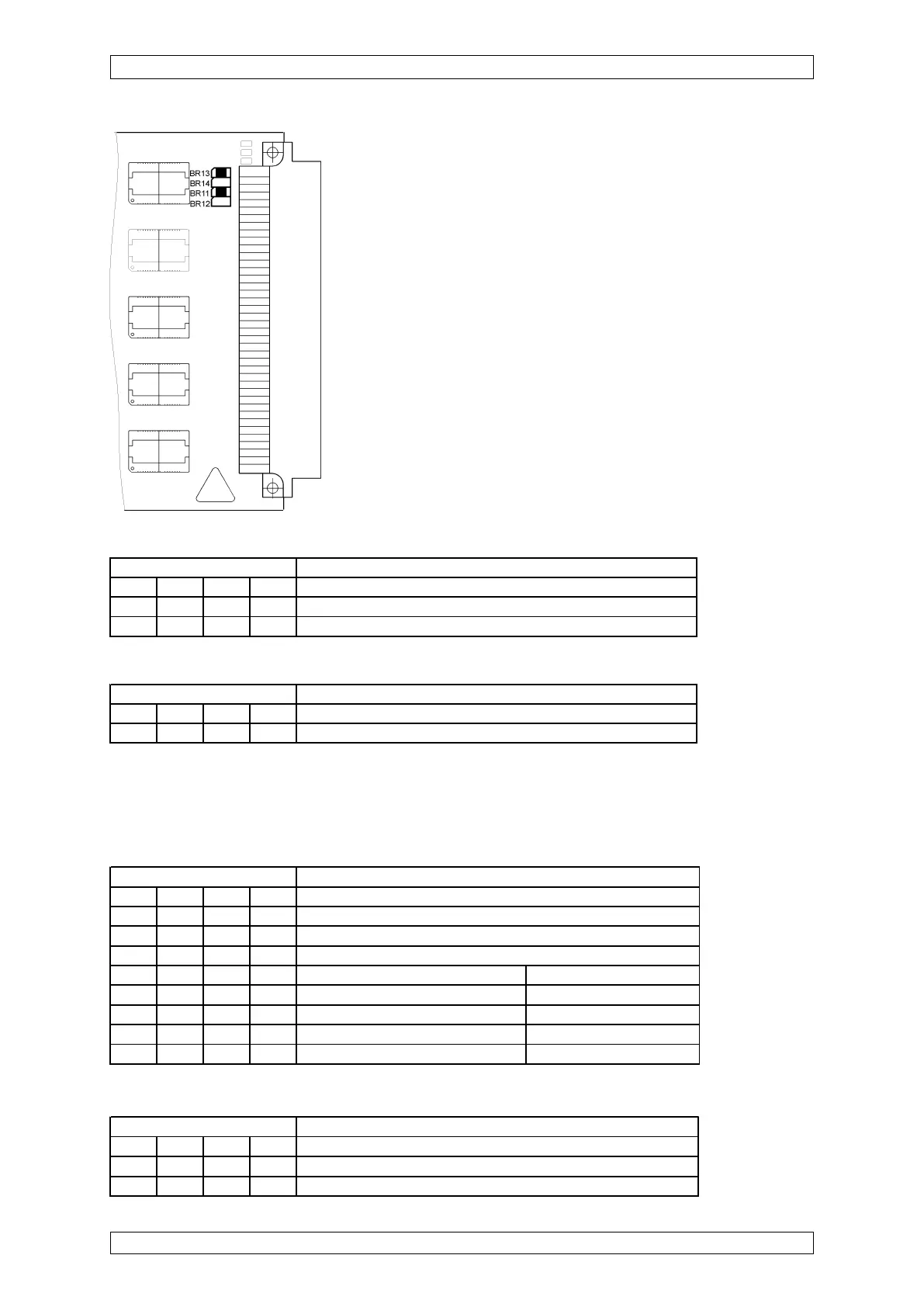
Figure 5-12: Configuration of the MGO Module
As of layout version 12, for SIL applications, the operating modes for control via CAN-A or
CAN-B buses, the turn-on behaviour must be configured with the S3 and S4 DIL switches.
FREE-A/-B settings
CAN-A/-B setting
* For SIL 3
operation, the
de-activation
function is set to
72 h.
Switch S3 Function
1234
OFF OFF ON ON Function by switch FREE-A/B by switch on the MIB modu
X X OFF OFF Function by switch FREE-A/B 1+2 on the MAO PCB
Relay behaviour
Behaviour at CAN failure Turn-on behaviour
OFF OFF OFF OFF Activated after 72 h Activated
OFF* ON* OFF* OFF* De-activated after 72 h* De-activated*
ON OFF OFF OFF Last state is kept Activated
ON ON OFF OFF Last state is kept De-activated
Switch S1 (as from layout version 15)
Switch S2
Switch S4 Function
1234
ON ON OFF OFF Control of the MGO PCB by CAN-A bus
OFF OFF ON ON Control of the MGO PCB by CAN-A bus
Switch S1 Function
1234
OFF OFF OFF OFF Factory setting (standard and SIL 3 operation)
OFF OFF OFF ON Only for MGO software version 1.02.01 and older
Switch S2 Function
1234
ON ON OFF OFF Factory setting/Do not change