REV 0, June 2005 Page 95
Operation Manual SUPREMA
5. Installation
The maximum length of a cable is calculated as follows
=
∗∗
, where R is the
maximum load in ohms, k = 56 (conductivity of copper);
and A is the cross section of the conductor in mm².
m
Ohm * mm
2
If no information is available on the maximum load, only the specified maximum length may be
used.
The maximum allowable length of the CAN bus can be found in the following table:
Bit rate in kBit/s
10 20 50 125 250 500 100
Maximum Bus Lenght in m
5000 2500 1000 500 250 100 2
Table 5-3: Maximum Allowable CAN Bus Length
Note: Cable must be laid in agreement with the previous EMC instructions and
regulations.
5.3 Module Configuration
The modules should be configured in the order given here with no voltage applied. In the case
of systems that have already been configured, the configuration of the individual modules must
be checked.
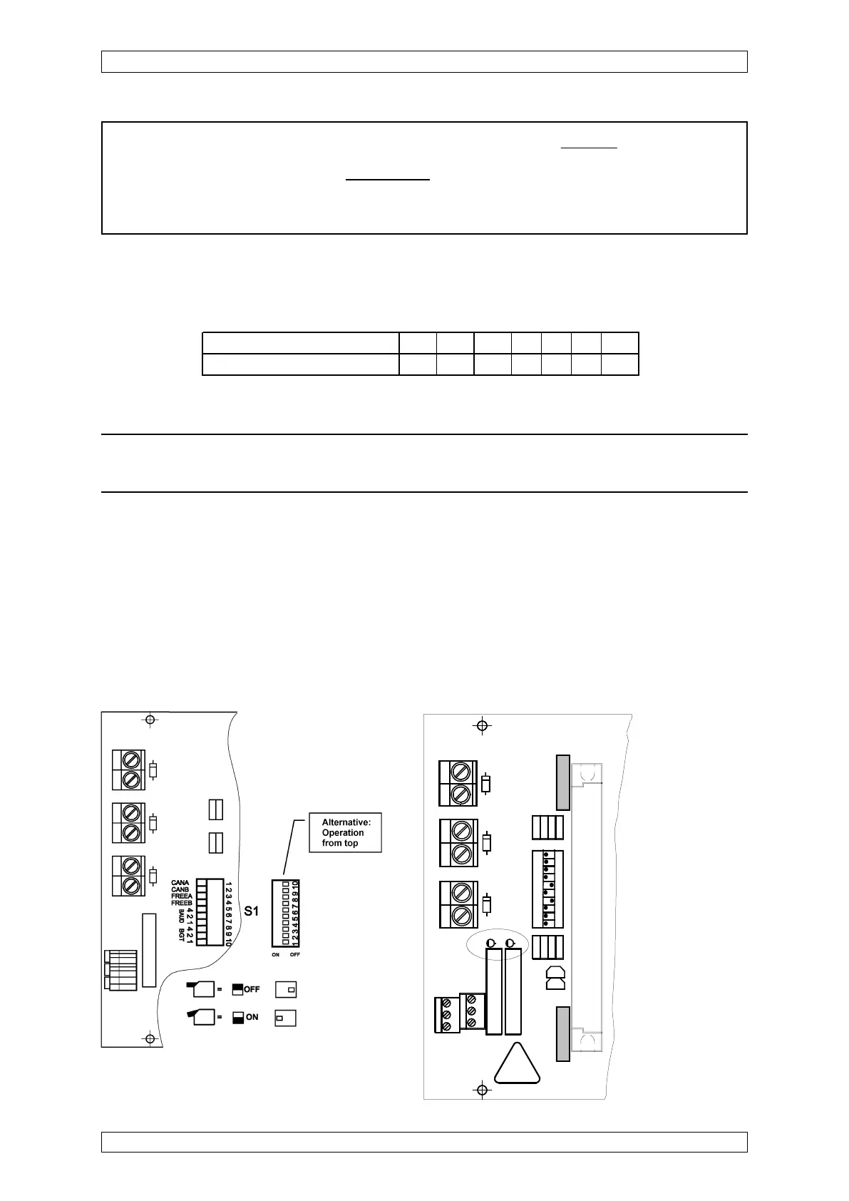
5.3.1 Configuration of MIB Module
A DIL switch is provided on the back of the MIB module. This switch is used to set the CAN bus
parameters.
Figure 5-2: MIB-Module, DIL Switch
(BGT = Rack No.)
MIB 20 as from
layout version 2
has 2 system
failure relays
(X601) for SIL 3
applications.
c
1
a
EXT
INT
+
-
C
2
1
X
2
1
C
1
1
+
+
D
1
1
P
O
S
1
0
X 15
1
2
BAT
X
2
3
S
1
D
1
3
R
5
2
R
4
2
R
3
R
2
R
1
1
R
1
2
R
1
3
R
1
4
T1
T2
R
L
2
R
L
1
X601
D2
D1
X
2
2
O
N
3
4
5
6
7
8
9
1
2
1
1
1
0
D
1
2
1
1
0