REV 0, June 2005 Page 145
Operation Manual SUPREMA
5. Installation
The connection of switching outputs via the MAT module or the MAT-TS module is not provided
for and
not allowed!
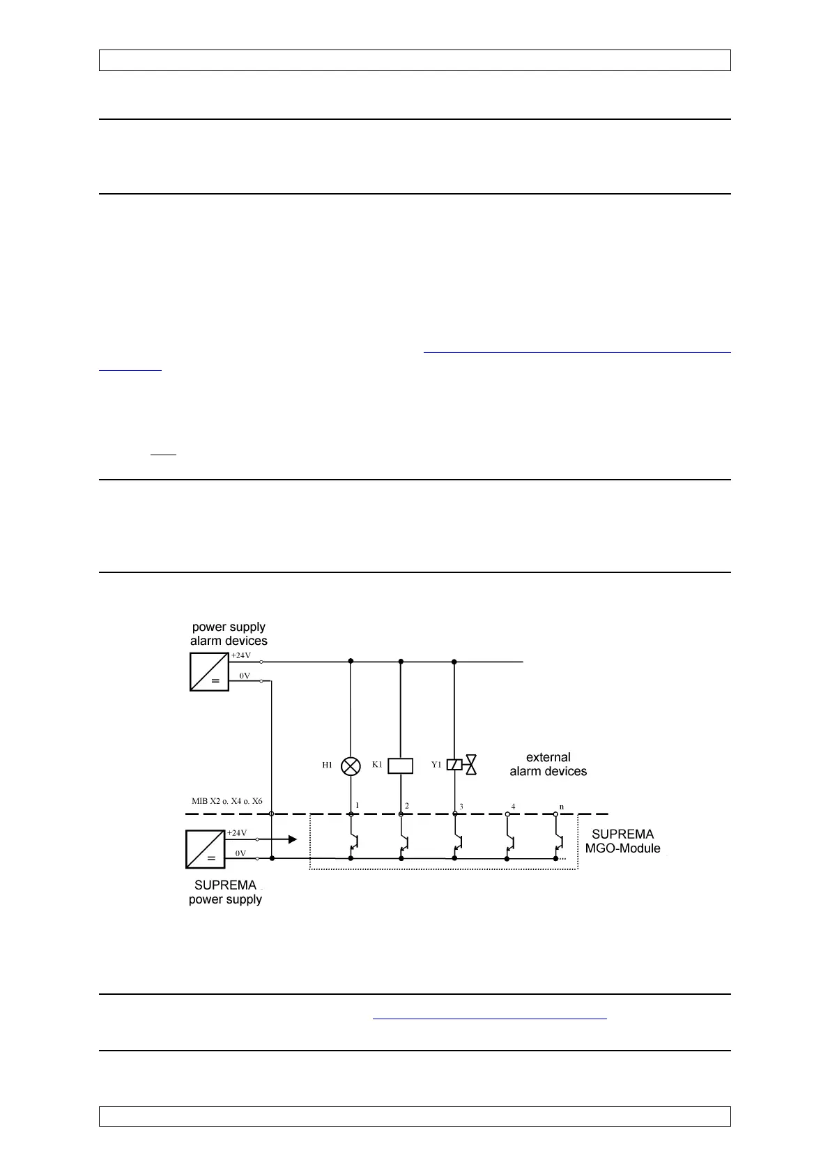
Note: The outputs from this module (maximum +24 VDC/300 mA) are referenced
to the SUPREMA ground. Therefore, the ground of the module supply voltage
must be connected to the ground of the SUPREMA (ground of the power supply
terminal at the MIB module).
Figure 5-36: Principle circuit diagram, connection of the switching outputs
Note: The load limits, described at chapter 5.4.3 „Maximum Loads“ must be
meet!
Note: Both system failure relays have to be interconnected such that the failure
report is triggered already when one relay is de-activated. This applies for
remote racks, too.
5.8 Connection of the Switching Outputs
Up to 512 switching outputs can be controlled by the system via the MGO module (40 open
collector drivers per module). These switching outputs can be used to drive relays, magnetic
valves, and LEDs (24 VDC/300 mA). It must be remembered that the first 8 switching outputs
of the first MGO module in the system are permanently assigned to the common alarms, whereas
the other outputs can be configured as desired
(see section 6.4.1 Configure the Relay Driver
Outputs). The switching outputs can be accepted by an MGT-40-TS module installed on a
mounting rail. The MGT-40-TS module must be connected to the MUT module assigned to the
MGO module card by a 40-way ribbon cable.