REV 0, June 2005Page 214
Operation Manual SUPREMA
9. Connection of Peripherals
This output is generated each time a change occurs in the status of a sampling point, that, is,
whenever the upper or lower alarm threshold is crossed (unless the alarm is self-locking),
whenever a signal error is received, and whenever a self-locking alarm or a signal error is
successfully reset manually (status no longer exists). The current status of the sampling point
with the data structure shown in
Figure 9-4: Protocol printer, Data Structure is printed out along
with the date and time of the most recent change of status.
9.3 Bus Connection
To connect the SUPREMA system to existing industrial control systems, it is necessary to
communicate with other data buses for processing of measuring values, alarms/failures.
The signal convertion necessary is realised by SUPREMA gateways.
Note: 2 gateways Per CAN channel can be connected.
Attention: The gateways are not included in the approval!
For the time being, the following bus systems are supported:
• MOD-Bus RTU Standard
• Profibus DP
Further data bus systems on request.
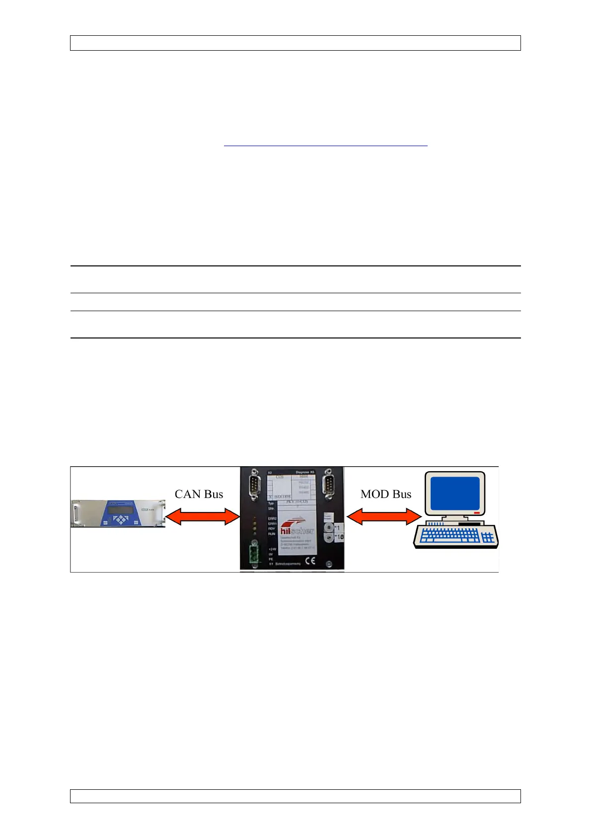
9.3.1 SUPREMA Gateway CAN/MOD-Bus RTU (PKV30)
(Not contained in EC type test approval DMT 03 ATEX G 003 X)
The gateway is installated on a mounting rail in the cabinet and requires a 24 V dc supply
voltage (X1). The SUPREMA transfers the data via the CAN bus which is connected to X2 at
the gateway. For data supply to the MOD bus, there are 3 physically different serial
interfaces (X3) and 3 different data formats to be selected.
The gateway generally operates as a slave for the CAN bus and MOD bus. The SUPREMA
and the control system must therefore initiate the gateway to send data.
Enclosed with the gateway are the following 5 manuals for installation, parameters and
operation:
• Device manual PKV 30-COS Protocol converter for CANopen Slave
• Bridge manual Transfer CANopen Slave to MSA AUER at the PKV30-COS
• Protocol manual Modbus coupling RTU Format (also called J-Bus)