REV 0, June 2005Page 220
Operation Manual SUPREMA
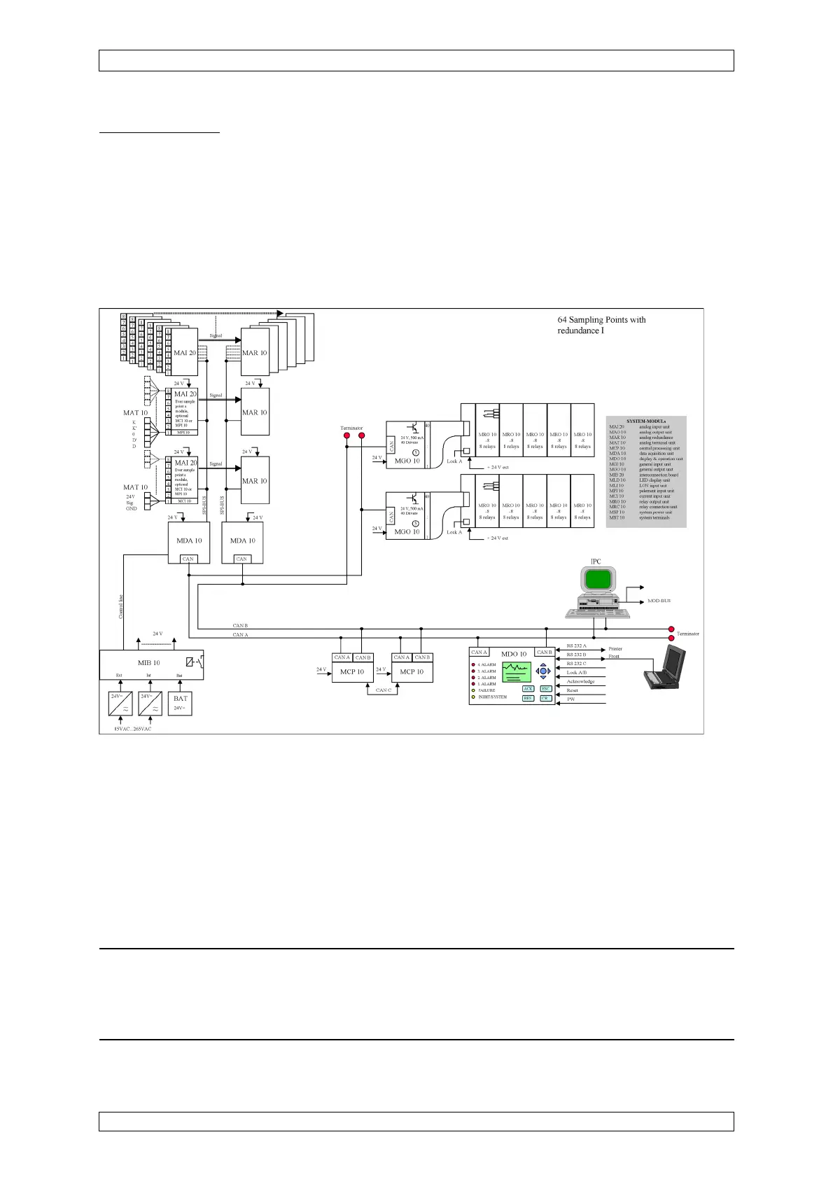
10. Redundant Systems
Module Functions
MDA Module = Measuring Signal Input
MCP Module = Measuring Signal Evaluation
MGO Module = Alarm Output
MAI Module = Analog Input (ADW 1)
MAR Module = Analog Redundant (ADW 2)
Figure 10-1: Circuit Diagram Rack System (redundant)
10.3 Design of the Redundant System
10.3.1 Components of the Rack
In the non-redundant version, the system is consists of only one channel (channel A). By
retrofitting modules for channel B, the system can be designed to be redundant in one rack for
up to 64 measuring points.
Attention: Retrofitting necessary modules for redundant design must only be carried
out voltage-free, i.e. the whole SUPREMA system must be switched off. The
following new startup must be carried out with consideration of the necessary
configuration and parameter setting steps.