REV 0, June 2005Page 116
Operation Manual SUPREMA
5. Installation
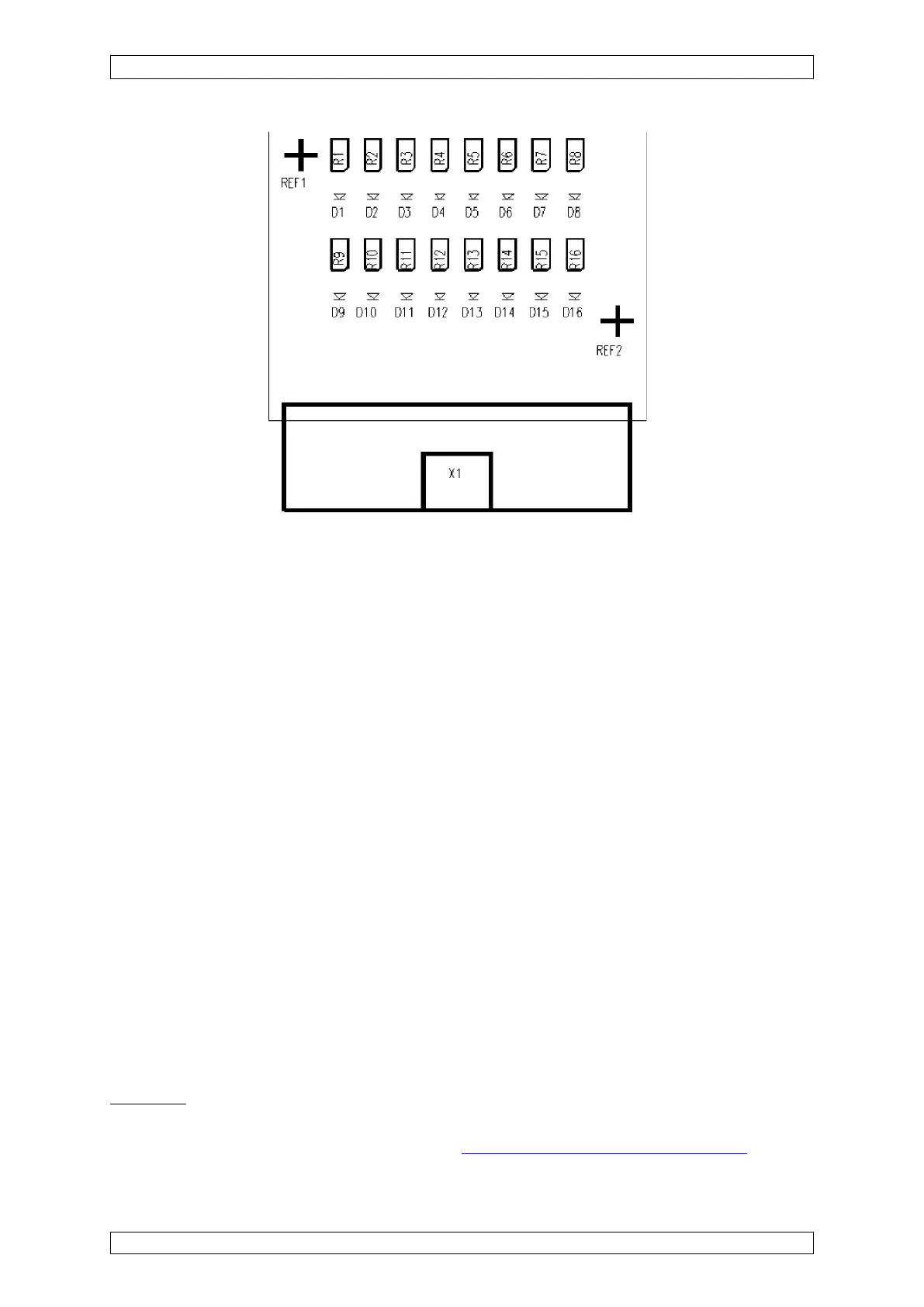
LED 1 – 8 = Driver outputs channel A
LED 9 – 16= Driver outputs channel B
Figure 5-21: View of MRD Module
5.4 System Configuration (Hardware)
5.4.1 Slot Assignments
After all the modules have been configured (or after their configuration has been checked), all
the required modules should be inserted into the racks or pushed from behind onto the contacts
and fastened in place mechanically by means of the retainers provided.
Assignment: Front: Rear:
Slot 1 ⇒ MST-Module
Slot 2–4 ⇒ free
Slot 5–15 ⇒ Pos 1–10
For each slot on the front there is a corresponding module connector plug on the rear. To install
modules that are to be inserted from the front (MCP module, MDA module, MAI module, MGO
module, and MAO module) detach the front plate and flip it down. The following rules should be
observed:
Front:
Slots 1–3:
The first 3 slots are reserved exclusively for the MCP module. In systems without redundancy,
slot 1 is the standard slot for the MCP module (see section 10 Redundant Systems).