REV 0, June 2005 Page 21
Operation Manual SUPREMA
2. System Concept
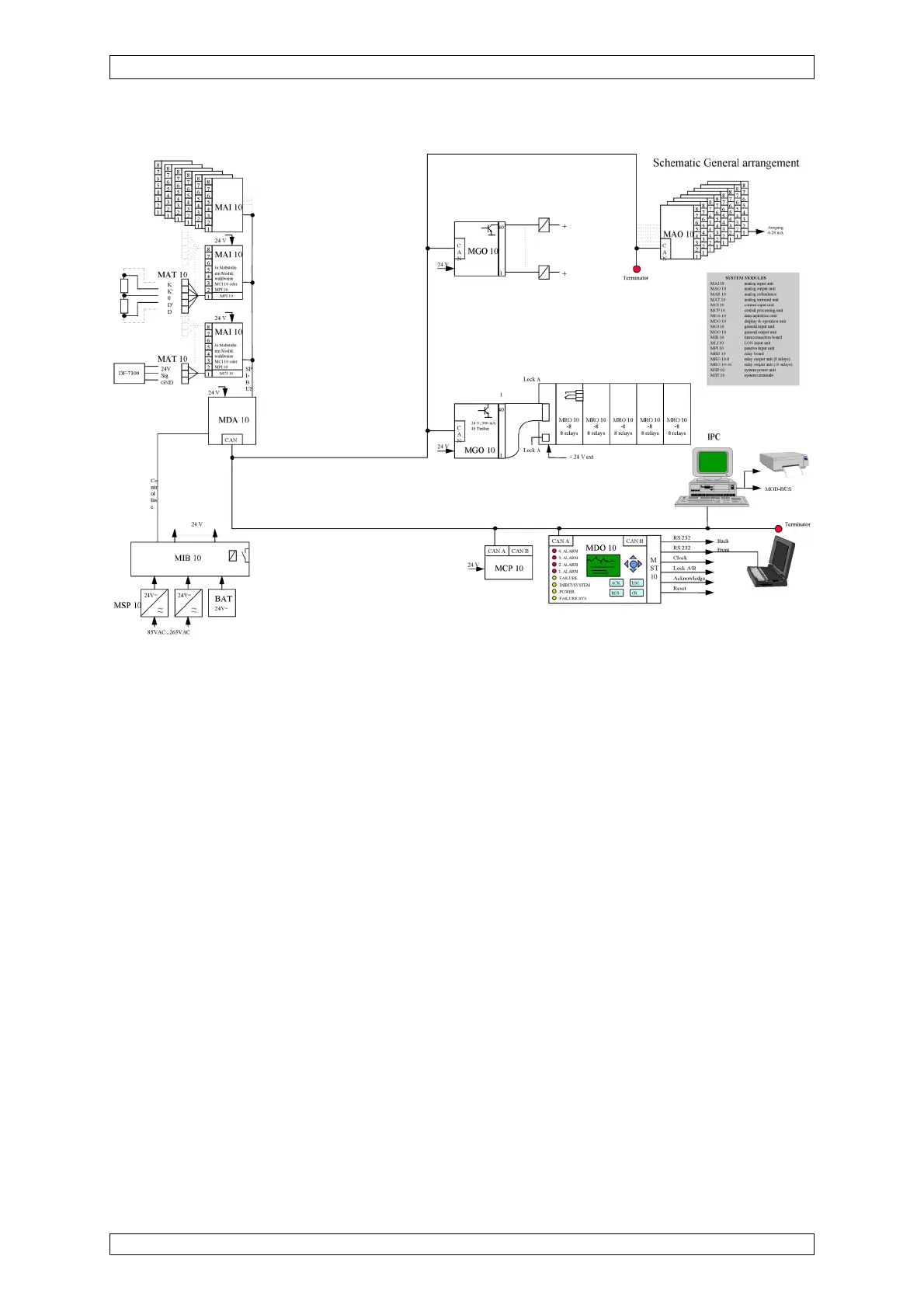
Figure 2-1: Block circuit diagram of a system layout (non-redundant)
2.4 Safety Concept
The individual functional modules are connected to each other by a CAN bus. The CAN bus is
designed to be virtually error-proof. Every module can detect errors on the bus and handle
them. The probability of an undiscovered communications error on the bus is 4.7
.
10
-14
. Error
states on the CAN bus are indicated on the DISPLAY + OPERATION unit.
Each module with a microcomputer module has a ”watchdog timer”, which actuates a ”wired
OR” signal line when the module fails. As a result, the SYSTEM FAILURE common relays on
the interconnection board (MIB module) are de-activated. This common failure signal is monitored
by the DISPLAY + OPERATION unit (MDO module).
All the modules are checked for signs of life at fixed, periodic time intervals by the CENTRAL
PROCESSING unit (MCP module) via the CAN bus. The failure of a module can thus be
recognised, and the appropriate messages will be generated. In addition, the DISPLAY + OPE-
RATION unit (MDO module) and at least one GENERAL OUTPUT Module (MGO module) are
able to detect at the local level when these regular checks do not occur, and they then pass this
information on. The operating voltages of the connected voltage supply units (EXT, INT and
BAT) are monitored by special inputs of the DATA ACQUISITION unit (MDA module). If a
malfunction occurs here, the POWER-FAIL common relay is released.