REV 0, June 2005Page 164
Operation Manual SUPREMA
6. Startup
Measuring Points
By means of the listing, the measuring points are configured. A maximum of 256 measuring
points max. can be configured, which can be distributed over 8 racks.
Channel Number
In this column, the numbers of the possible physical measuring points (0–255) are listed. Up to
32 MAI cards each with 8 inputs (32 x 8 = 256) can be connected (rack 1 to rack 8). Rack 1 has
the numbers of the physical measuring points 0 to 63.
Measuring Point Number
Here, the “logical” measuring point numbers are entered which are selected as “measuring
point” in the parameter setting. The measuring point numbers may be assigned freely. To avoid
configuration problems, standard numbering is recommended
(see figure 6-3 Measuring point
map listing). For rack 1, the measuring point numbers 1–64 are provided as standard.
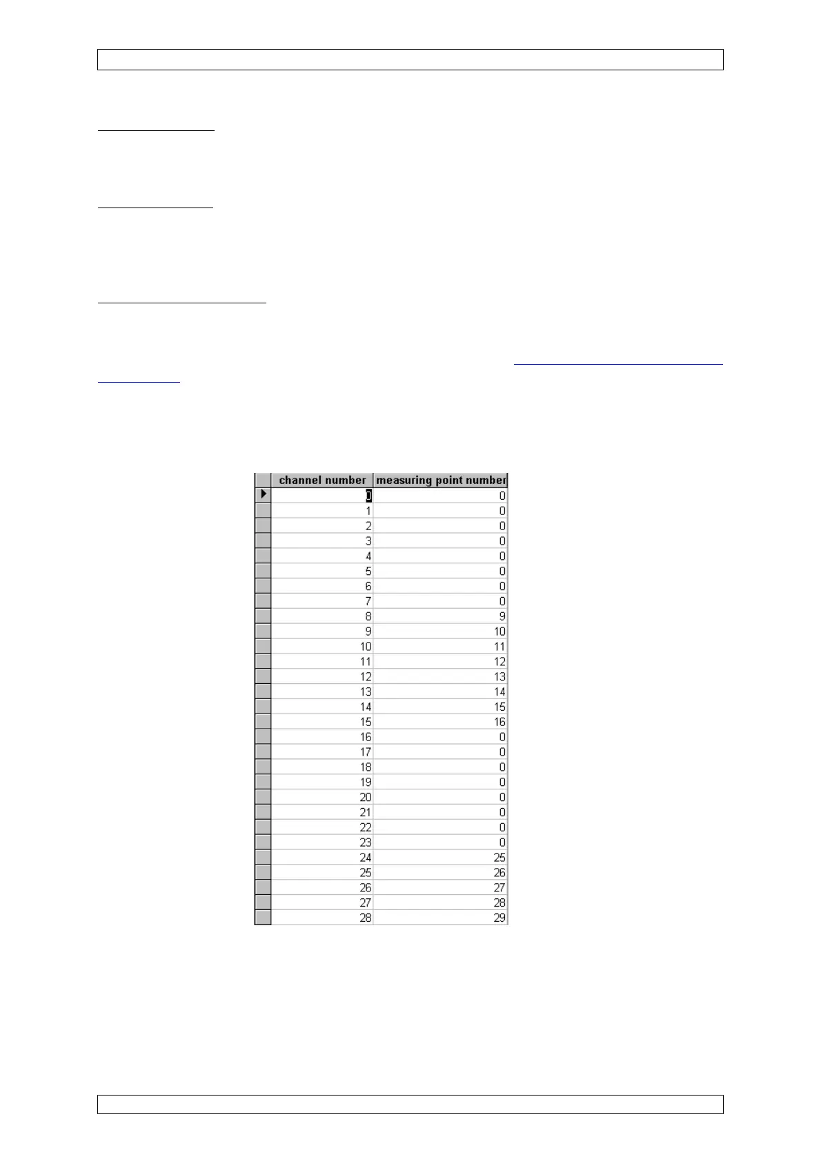
Example:
Only measuring points 9–16 and 25–26 shall be operated. In this case, the following listing is
generated: View of the “measuring point map” listing:
Figure 6-3: „Measuring point map” listing
All measuring points which are not needed are set to “0” (Zero) in the field “Digital Output
Number”.