REV 0, June 2005 Page 103
Operation Manual SUPREMA
5. Installation
Equivalent to Equivalent to
X1/1-X1/2 X1/4-X1/5
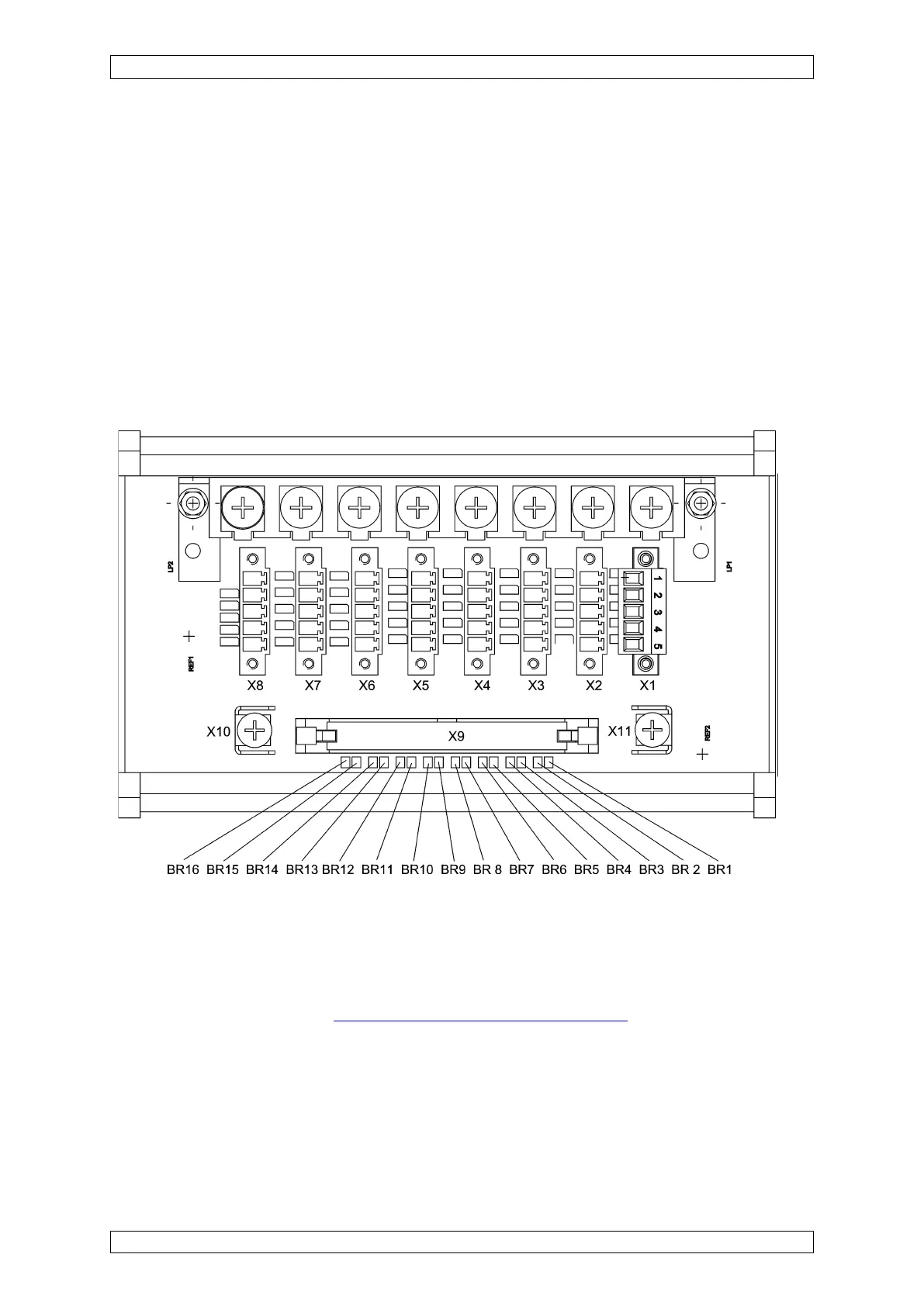
Assignment: BR1, BR2 ⇒ input 1
BR3, BR4 ⇒ input 2
BR5, BR6 ⇒ input 3
BR7, BR8 ⇒ input 4
BR9, BR10 ⇒ input 5
BR11, BR12 ⇒ input 6
BR13, BR14 ⇒ input 7
BR15, BR16 ⇒ input 8
Figure 5-7: Configuration of the MAT-TS module
5.3.6 Configuration of the MRO-8-module
On the module, there is a solder bridge (BR1), which is used to define the function of the relay
inhibit of the common alarms
(see section 5.10.7 LOCR Connection) is established:
Solder bridge BR1 = OPEN = relays are energised when the relay inhibit is turned on
Solder bridge BR1 = CLOSED = relays are de-energised when the relay inhibit is turned on