REV 0, June 2005Page 64
Operation Manual SUPREMA
4. Operation of the System
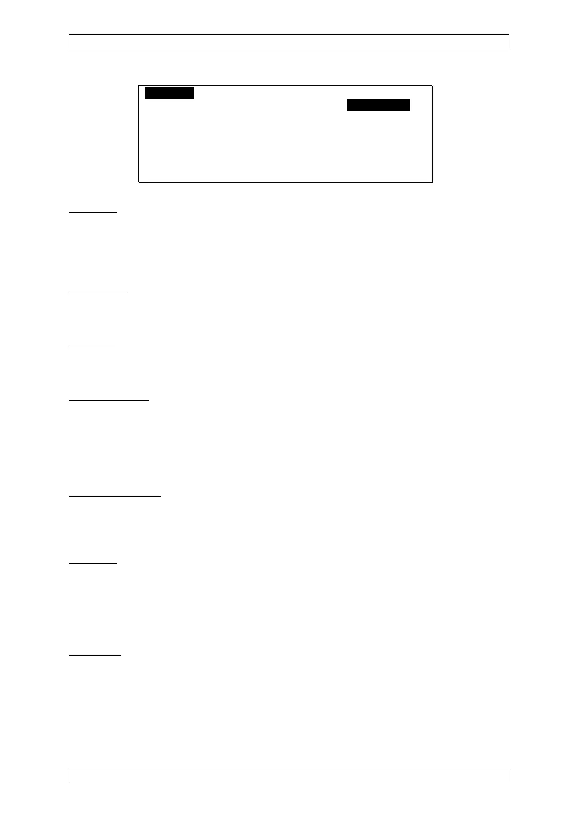
Logbook MeasureData Menu A
[Measure Point] [Modules]
Module-ID: 2 Partial System: B
Module Type: MCP-10
Serial-No.: 1234546789
Software-Version: 1.02.03b
no actual errors
[Cancel]
Figure 4-17: “Modules” submenu
Module ID
Field type: Selection
This field contains the ID code Nos. of all system modules which are connected to the CAN
bus. After an ID code No. has been selected, the remaining menu is filled with all data available
for this particular module.
Module Type
Field type: Display
This field contains the type of module selected.
Serial No.
Field type: Display field
This field contains the serial number of the module selected.
Software version
Field type: Display
This field displays the software version of the module selected.
“Measure Point”
This submenu displays the current information on all inputs.
Measure Point No.:
Field type: Selection
After selection of a measure point No., in the appropriate display field, the current signals of the
selected point are displayed.
Signal UA:
Field type: Display
The amplified sensor signal is displayed in this field. The signal UA corresponds to the signal
that is applied to the test sockets of the MAI module, after selection of the corresponding input
No., and consists of a fixed and a variable amplified quantity. Therefore the non-amplified
sensor signal cannot be calculated directly.
Signal UQ:
Field type: Display
When passive sensors and MPI modules are used, the bridge current is displayed as a voltage
value.
When active sensors and MCI modules are used, dashes are displayed in this field.