REV 0, June 2005 Page 159
Operation Manual SUPREMA
5. Installation
5.12.2 Slots in the Rack
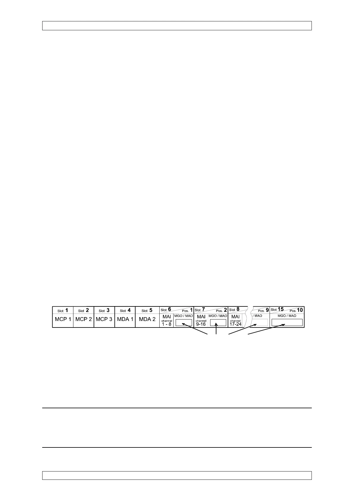
In the rack, a labelling field is provided in front of the slots. The slot nos. and the types of
modules allowed for each slot are printed on it. In the first rack, the input numbers assigned to
the slot are also printed on this field (in the case that the slot has been filled with an MAI
module). In addition, the customer also has the possibility of marking the type of module
actually used in each slot, and, when MGO or MAO modules are used, of entering the output
channel no. corresponding to the position of the module in the system. When several racks are
installed and MAI modules are being used, it is necessary to enter the input nos., starting with
the second rack, corresponding to the position in the system.
The following rules apply to the numbering of the input and output channels:
MAI Modules/Measurement Sites:
The input nos. are assigned permanently to the slots in the rack; 8 inputs can be connected per
MAI module. For example, if the first MAI module has been plugged into the 7
th
slot in the first
rack, the first 8 inputs acquire the nos. 9-16.
MGO Modules/Relay Driver Outputs:
The relay driver output nos. are assigned to the MGO module; each MGO module makes 40
relay driver outputs available. That is, regardless of the slot no. and the rack no., the relay
driver outputs of the first MGO module acquire the nos. 1–40, those of the second MGO module,
the nos. 41–80, etc.
MAO Modules/Analogue Outputs:
The analogue output nos. are permanently assigned to the input nos.; 8 analogue outputs are
available per MAO module. The first MAO card plugged into the system provides the analogue
outputs for input nos. 1–8, the second provides the analogue outputs for input nos. 9–16, etc.,
regardless of whether a MAI module is present or not. If, for example, the first MAI module has
been plugged into the 7
th
slot of the first rack (input nos. 9–16), then the analogue signals of the
first 8 sensors are sent to the second MAO module plugged into the system (analogue outputs
9–16).
Figure 5-48: Labelling of the slots in the 1
st
rack
5.12.3 Connection and Terminal Modules on the Rack
A free labelling field is provided for the modules plugged into the rear of the rack (MRO-8, MAT,
and MUT modules). The following rules apply to the assignment of the rear plug positions to
the slot numbering on the front:
Assignment: Front: Rear:
Slot 1 ⇒ MST module
Slot 2-4 ⇒ free
Slot 5-15 ⇒ Positions 1–10