REV 0, June 2005Page 224
Operation Manual SUPREMA
10. Redundant Systems
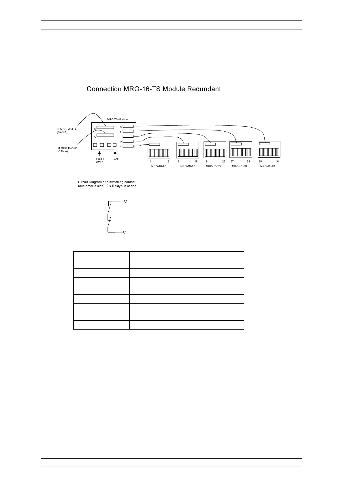
The 40 driver outputs of the MGO module of channel A are connected to the MRC-TS modules
at Plug A using a 40-way ribbon cable via the appropriate MUT module at the rear of the rack.
The 40 driver outputs of the MGO module of channel B are connected to the MRC-TS modules
at Plug B using a 40-way ribbon cable via the appropriate MUT module at the rear of the rack.
Figure 10-4: Connection MRO-16-TS Module
Connection Terminals Relays Function at Position 1, (first relay block
1-2 1, 9 1st Alarm
3-4 2, 1 2nd Alarm
5-6 3, 11 3rd Alarm
7-8 4, 12 4th Alarm
9-10 5, 13 Failure measuring value
11-12 6, 14 Horn
13-14 7, 15 Inhibit
15-16 8, 16 Failure Power
Table 10-2: Terminal Connections MRO-16-TS Module
Relays specified are connected in series to effect hardware redundancy. The relays 1–8 are
selected by CAN A (MCP A), the relays 9–18 by CAN B (MCP B).