REV 0, June 2005 Page 135
Operation Manual SUPREMA
5. Installation
5.6.3 Note for Operation with Active Sensors (0/4 ... 20 mA)
At use of MCI 10-Modules Order No 10021029 and 10041567: The requirements of line control
according to EN50054 are not met with 3-conuctor operation in case of short-circuit of the
signal output of the remote measuring head against GND.
This note is invalid if using the MCI 20-Modules Order No 10043997 and 10044020. This
Modules are without any qualification operative.
5.6.4 Overview of the Terminal Assignment
In the following, an overview is presented of the assignment of the terminals. If the sensors are
to be connected directly to the rack, the MAT module is to be used. For remote connection
(installation on a mounting rail), the MAT-TS module (maximum conductor cross section, 1.5
mm
2
; sensors can be electrically isolated individually) or the MGT-40-TS module (maximum
conductor cross section, 2.5 mm
2
; 8 sensors per module, can be isolated electrically only as a
group) can be used. The remote modules are connected to the MUT module on the rack by the
associated ribbon cable.
MAT Module/MAT-TS Module/Sensor Connections
The function of the terminal connections of the MAT/MAT-TS module depends on the module
card plugged into the rack.
Table 5-20: MAT-/MAT-TS Module, Terminal Assignment, Sensor Connections
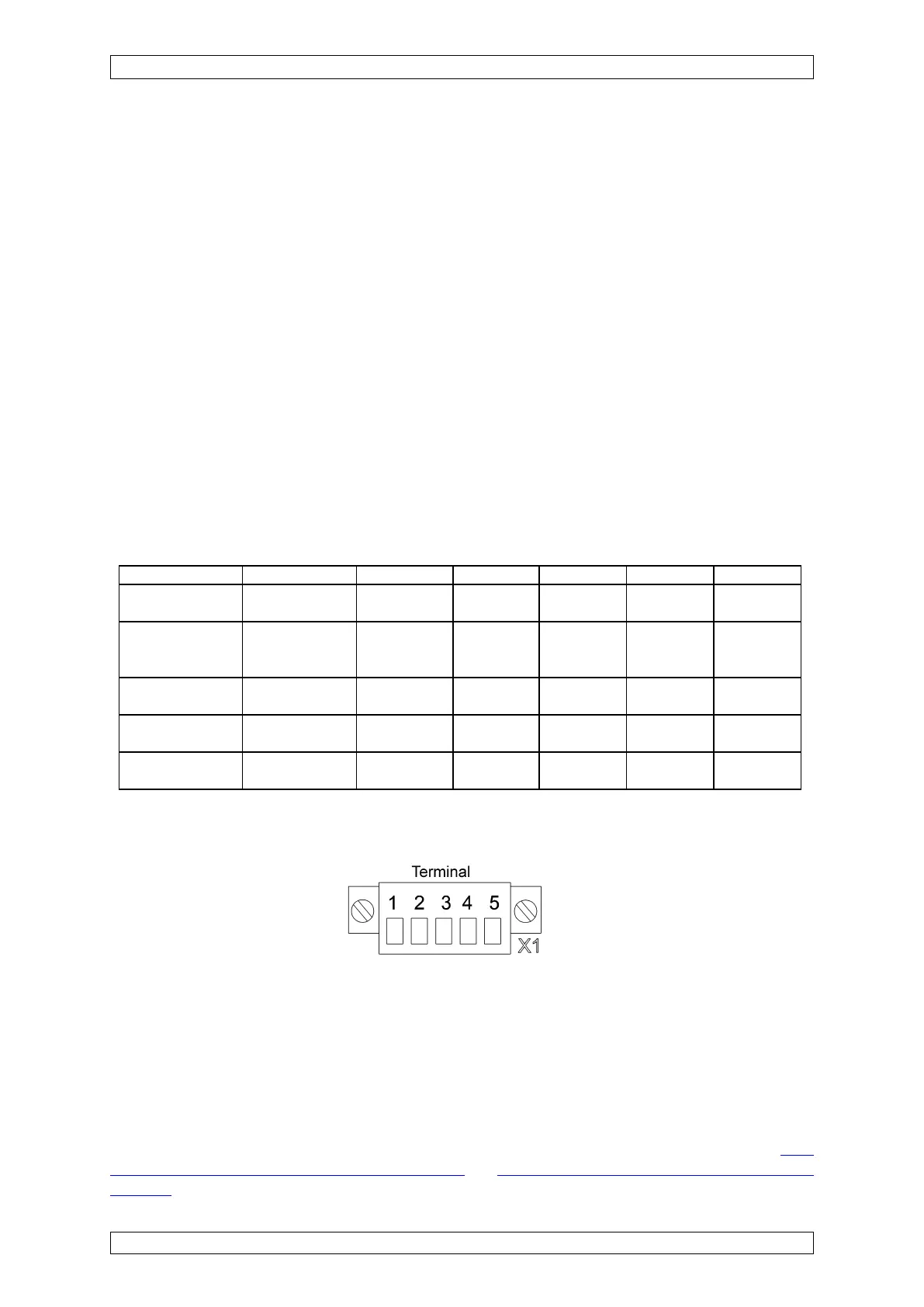
Figure 5-30: MAT Module/MAT-TS Module, Connector Plug
For the 3-wire operation of the passive WT sensors, bridges are to be provided:
Terminals 1–2: BR K–K’
Terminals 4–5: BR D–D’
If wire jumpers cannot be installed at the terminals, they can be provided on the rear of the MAT
module in the form of solder bridges. (next to the ribbon plug of the MAT-TS module).
(see
section 5.3.4 Configuration of the MAT Module and section 5.3.5 Configuration of the MAT-TS
Module)