REV 0, June 2005Page 216
Operation Manual SUPREMA
9. Connection of Peripherals
Setting the CANopen node address:
For the gateways, the CANopen node numbers
124 Code switch 1 = C; 16 = 7 (1*C+16*7=124)
125 Code switch 1 = D; 16 = 7 (1*D+16*7=125)
are provided.
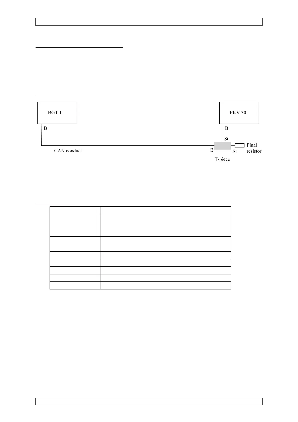
Connection to the SUPREMA:
Figure 9-5: Connection Suprema Gateway CAN/MOD-BUS RTU
The CAN terminating resistor of rack 1 has not been set, therefore at the T-piece of the PKV 30
a terminating resistor is connected.
Technical Data:
Supply voltage 18 ... 30 V at 24 V, the supply current is: 200 mA max.
Plug connector X 1: COMBICON for supply voltage
X 2: 9-pin D-SUB for CANopen Interface
X 3: 9-pin D-SUB for RS 232, 485 and 422 Interface
LED displays Ready and communication, failure of the serial interface
SCL 1, Status CANopen.
Temperature range 0 ... 50 °C
Type of protection IP 50
Dimensions (L x W x H) 105 x 105 x 80 mm
Weight 500 g
Mounting Mounting rail DIN EN 50022
Table 9-1: Technical Data Suprema Gateway CAN/MOD-Bus RTU