REV 0, June 2005 Page 151
Operation Manual SUPREMA
5. Installation
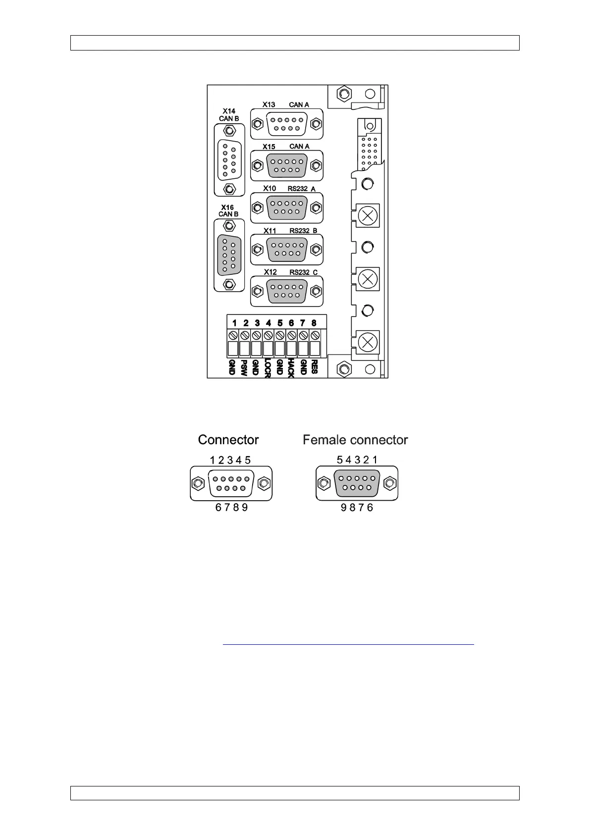
Figure 5-42: MST Module Connections as from PCB version 8
Figure 5-43: SUB-D pin assignment
5.10.1 CAN Bus Ports (CAN-A/CAN-B)
The two system buses in the system, i.e., CAN-A and CAN-B, are provided to allow expansion
of the system (systems with several racks). The measurement value input (MDA+MAI module)
or the switching outputs (MGO module) can be set up separately from the main rack to reduce
the cabling. In systems without redundancy, the individual racks are connected to each other
by ready-made CAN bus cables via the CAN-A bus port (see Section Fehler! Verweisquelle
konnte nicht gefunden werden.
(see section 5.4 System Configuration – Hardware).