REV 0, June 2005Page 144
Operation Manual SUPREMA
5. Installation
Figure 5-34: MRO-8-TS-Module
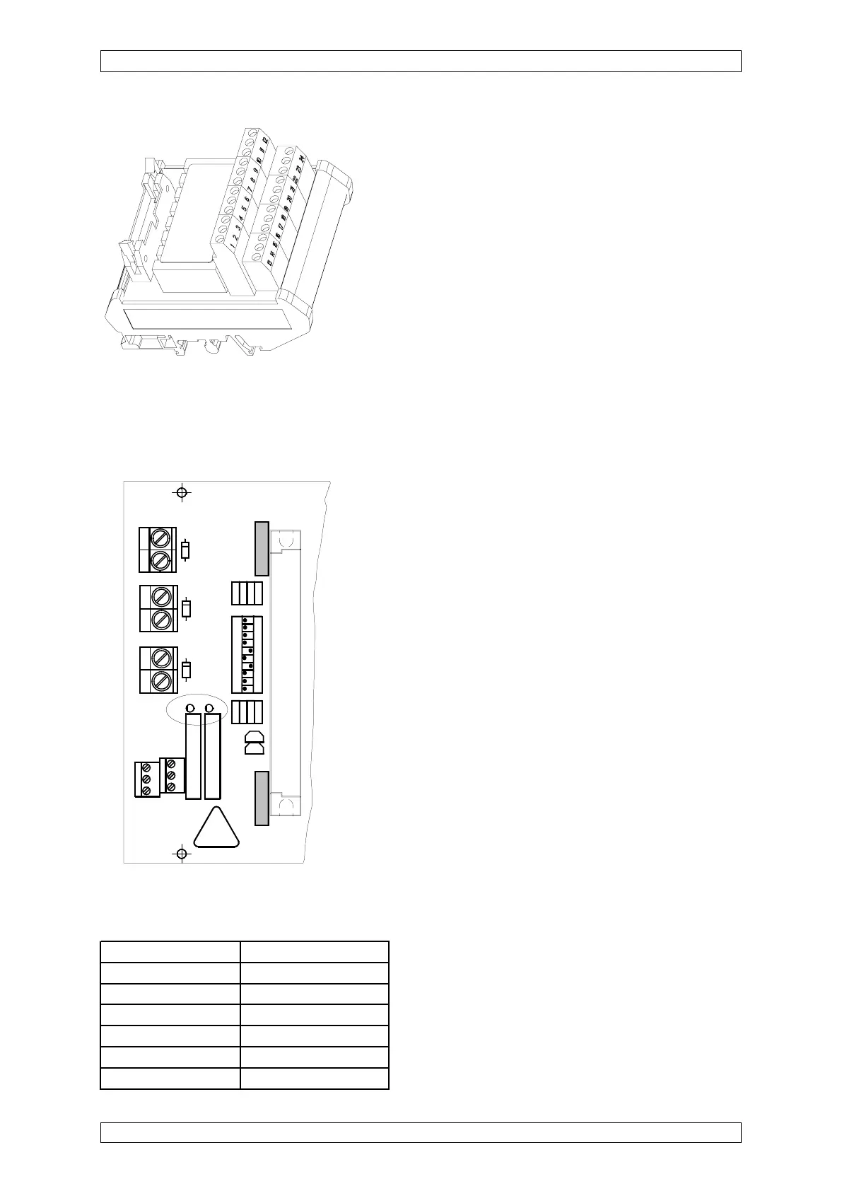
5.7.3 System Failure Relay
There are two system failure relays on the MIB module, designed as changeover contacts.
They are operated according to the normally energised principle. Both relays are de-energised
when a failure occurs. The terminal contacts are directly next to the relays on the MIB module.
Terminal Assignment:
Table 5-28: MIB Module, System Fail Relay, and
Terminal Assignment
c
1
a
EXT
INT
+
-
C
2
1
X
2
1
C
1
1
+
+
D
1
1
P
O
S
1
0
X 15
1
2
BAT
X
2
3
S
1
D
1
3
R
5
2
R
4
2
R
3
R
2
R
1
1
R
1
2
R
1
3
R
1
4
T1
T2
R
L
2
R
L
1
X601
D2
D1
X
2
2
O
N
3
4
5
6
7
8
9
1
2
1
1
1
0
D
1
2
1
1
0
Figure 5-35: MIB Module, connection terminals for the system
failure relay
X 601 Terminal No. Contact
7 Break contact relay 1
8 Centre contact relay 1
9 Make contact relay 1
10 Break contact relay 2
11 Centre contact relay 2
12 Make contact relay 2