REV 0, June 2005Page 150
Operation Manual SUPREMA
5. Installation
An external device with voltage input (e.g. recorder, PC with a DAQ card) can be connected to
the analogue outputs by connecting a resistor across the input terminals of the recorder. When
a 100-Ohm resistor is used, a voltage range of 0 ... 2 V is obtained for a 0 ... 20 mA signal.
Attention: Maximum load 500 ohms. The accuracy of the measured voltage
depends on the tolerance of the resistor used.
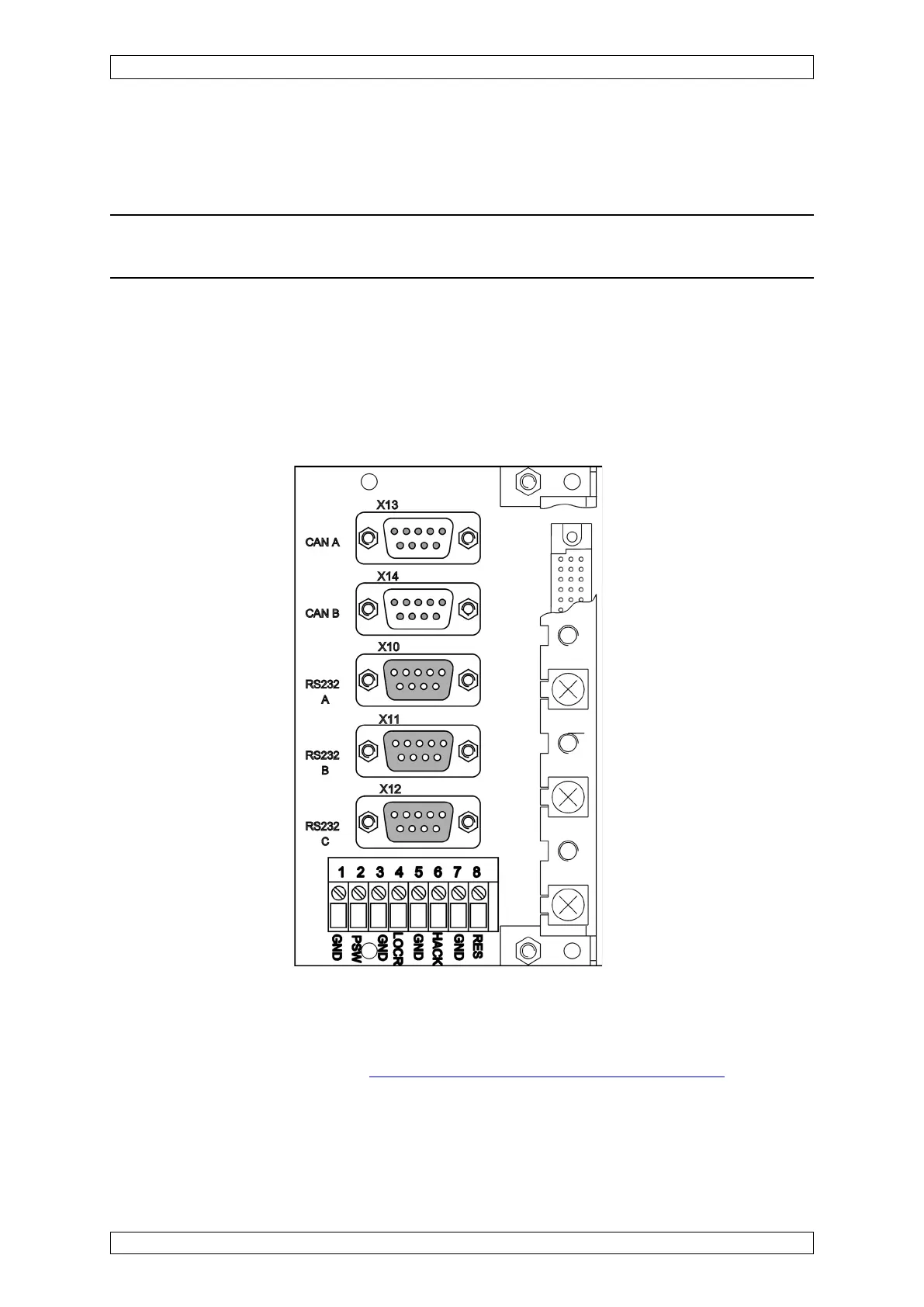
5.10 System Ports (MST Module)
The system expansions and system connections described in the following can be realised by
using the MST module, plugged into the rear of the rack.
Figure 5-41: MST Module ports, Connections
For simplification of the CAN bus connection at systems with several racks, the MST module
has been revised. For every CAN bus an additional connection was added so that the T pieces
are saved when connecting racks
(see section 5.5 Consisting of Several Racks).