REV 0, June 2005 Page 165
Operation Manual SUPREMA
6. Startup
Modules
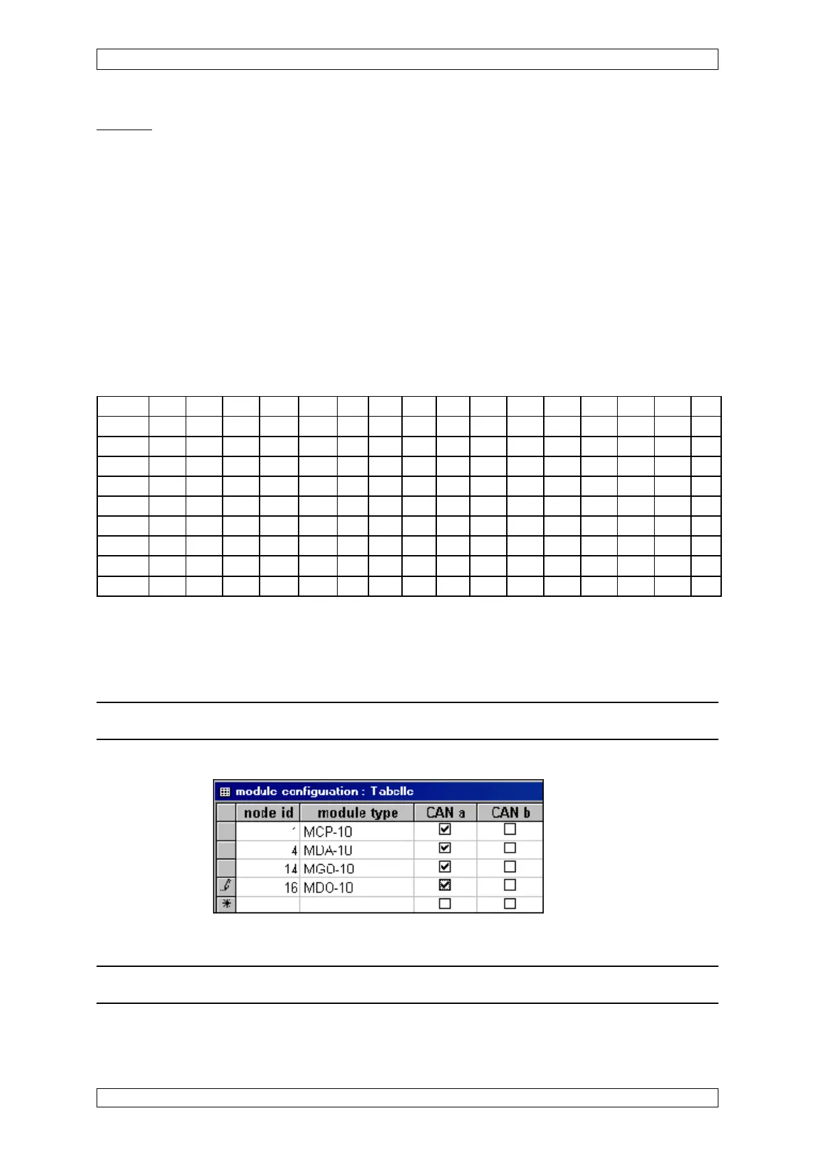
By means of this listing, the modules are assigned to the rack slot positions.
MAI modules need not be configured.
In the column “node id”, the slot number is entered, where the module specified under “module
type“ has been plugged.
In the columns “CAN-A/CAN-B”, the function is selected accordingly.
The MDO is aaigned to slot number 16 for the 1
st
rack and is defined as CAN-A.
For further racks, the “node id” is increased by 16, according to the rack number.
e.g. for Rack 2, the first MCP has the node ID 17 for Rack 3, the first MCP has the node ID 33,
etc.
Listing of node id (NID) of the Racks
Slot 1 Slot 2 Slot 3 Slot 4 Slot 5 Slot6 Slot 7 Slot 8 Slot 9 Slot10 Slot11 Slot12 Slot13 Slot14 Slot15
1.MCP 2.MCP 3.MCP 1.MDA 2.MDA X X X X X X X X X X MDO
1st Rack1 2 3 4 5 6 7 8 910111213141516
2nd Rack 17 18 19 20 21 22 23 24 25 26 27 28 29 30 31 32
3rd Rack 33 34 35 36 37 38 39 40 41 42 43 44 45 46 47 48
4st Rack 49 50 51 52 53 54 55 56 57 58 59 60 61 62 63 64
5st Rack 65 66 67 68 69 70 71 72 73 74 75 76 77 78 79 80
6st Rack 81 82 83 84 85 86 87 88 89 90 91 92 93 94 95 96
7st Rack 97 98 99 100 101 102 103 104 105 106 107 108 109 110 111 112
8st Rack 113 114 115 116 117 118 119 120 121 122 123 * * 126 127 128
Table 6-1: Listing of Node ID
X = MGO or MAO
*MOD-Bus Gateway (PKV 30) has address 124 or 125, according to the setting at the gateway.
Attention: No moduls may than being put in these places in the 8
th
rack.
View of the “module configuration” listing:
Figure 6-4: “Module configuration” listing
Note: For Simplex systems (non-redundant) always select CAN a.