REV 0, June 2005 Page 221
Operation Manual SUPREMA
10. Redundant Systems
Note: When retrofitting, the Regulations for Handling Electrostatic Sensitive
Components must be followed!
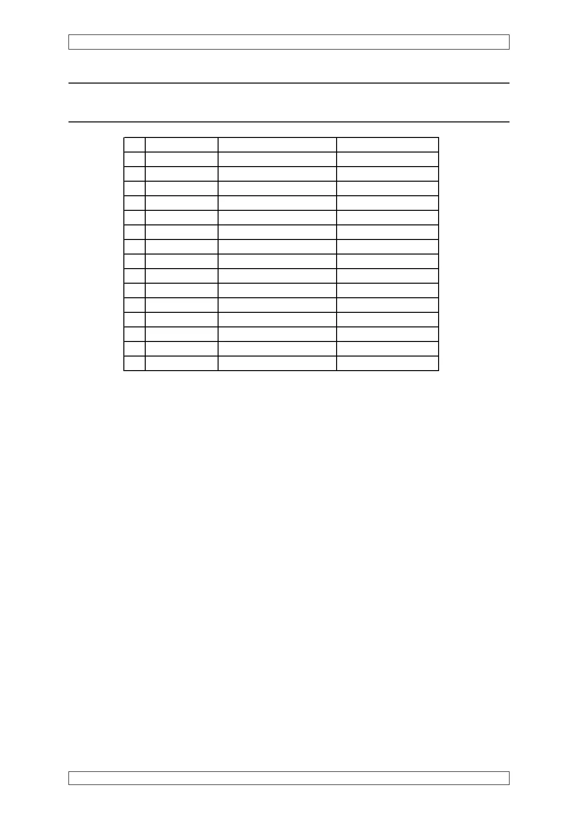
Slot Name Non redundant (Channel A) Redundant (Channel B
1 MCP1 MCP + MDO MCP + MDO
2 MCP 2 MCP
3MCP 3
4 MDA 1 MDA MDA
5 MDA 2 MDA
6 SLOT 6/POS 1 MAI MAI + MAR
7 SLOT 7/POS 2 MAI MAI + MAR
8 SLOT 8/POS 3 MAI MAI + MAR
9 SLOT 9/POS 4 MAI MAI + MAR
10 SLOT 10/POS 5 MAI MAI + MAR
11 SLOT 11/POS 6 MAI MAI + MAR
12 SLOT 12/POS 7 MAI MAI + MAR
13 SLOT 13/POS 8 MAI MAI + MAR
14 SLOT 14/POS 9 MGO MGO
15 SLOT 15/POS 10 MGO
Table 10-1: Modules of the Rack
By adding further racks (8 max. per system) and the appropriate modules, the system can be
extended up to 256 measuring points with up to 512 outputs.
• The MAR modules are plugged into the MAI modules.
• The MGO modules: configuration is by plug-in jumpers for CAN A or CAN B
• The same number of MGO modules at CAN A and CAN B
• Connection of 2 gateways at CAN A and CAN B (MOD Bus, Profi bus)
10.3.2 Installation of the MAR Module
This module is used for redundant evaluation of the input signals together with a second,
redundant MDA module.
It is plugged on the MAI module. The analog ouput signals of the MPI module or MCI module
are digitised in parallel to the MAI module by a 12 bit ADC, and are transferred to the second
MDA module via its own SPI Bus.
Here, the function is identical to the MAI module.
For connecting the MAR module, the MAI module has to be unplugged from the rack which
must be voltage-free. For every MAI module, a MAR module is necessary.