REV 0, June 2005Page 200
Operation Manual SUPREMA
7. Maintenance and Service
7.6.2 MAI-Module
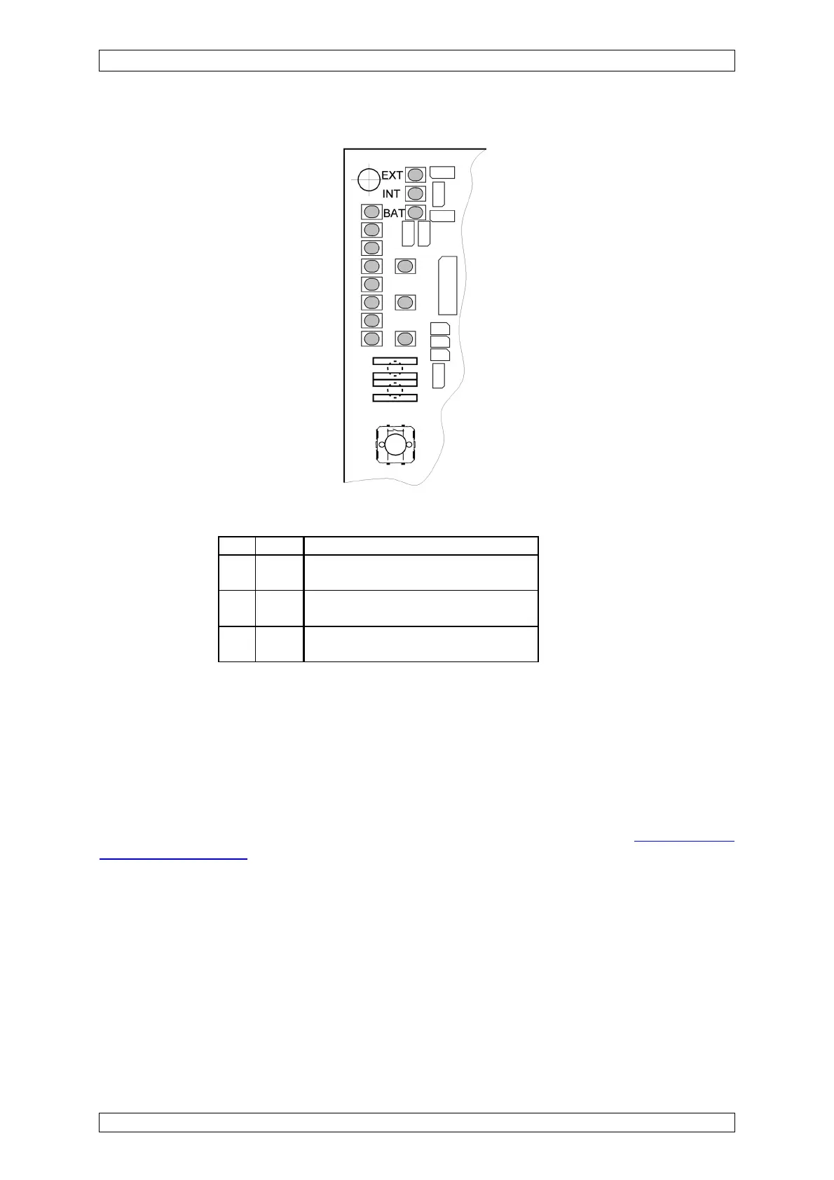
Figure 7-3: MAI module, Status LEDs
LED Color Function
EXT green ON: The external voltage supply is
connected to the module.
INT green ON: The internal voltage supply is
connected to the module.
BAT green ON: The battery voltage supply is
connected to the module.
Table 7-2: MAI Module, Function Status LEDs
In the normal case, only one of the first 3 LEDs is lit. If no LED is lit, there is a problem with the
voltage to the module.
7.7 Diagnostic Functions
The structure and operation of the “Diagnosis” menu are described in detail in section 4 Ope-
ration of the System. In the following, some of the more important functions are described in
greater detail.
The “Diagnosis” menu is divided into the submenus “Logbook” and “Measuring Data”.
In the “Logbook” menu, a series of failures and incidents is stored and can thus be used to
conduct an incident verification procedure at a later time.
The current status of the system, however, can be reviewed in the “Measuring Data” menu.
7.7.1 Logbook Functions
The logbook is divided into five history menus:
• Calibration