REV 0, June 2005 Page 199
Operation Manual SUPREMA
7. Maintenance and Service
7.6.1 MCP, MDA, MGO, MAO Modules
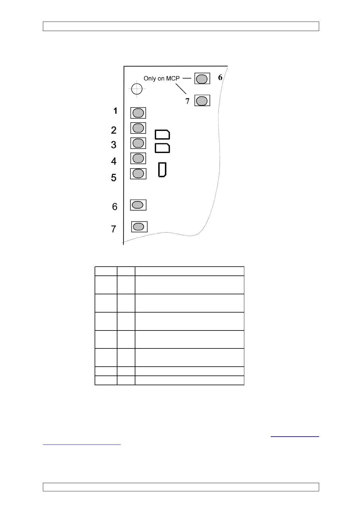
Figure 7-2: MCP, MDA, MGO, MAO modules, Status LEDs
LED-No. Color Function
1 green ON: The external voltage supply is
connected to the module.
2 green ON: The internal voltage supply is
connected to the module.
3 green ON: The battery voltage supply is
connected to the module.
4 red ON: A failure has occured
in the module
5 green ON: The module's CAN bus commu-
nications are proceeding correctly.
6 yellow ON: system reset
7 yellow ON: voltage failure
Table 7-1: MCP, MDA, MGO, MAO Modules, Function Status LED
In the normal case, only one of the first three LEDs is on. If no LED is on, there is a problem with
the voltage supply to the module.
If the failure LED (LED No. 4) is on, you should contact an MSA service technician. If this cannot
be done right away, the module can be replaced if a spare unit is available
(see section 7.4
Replacement of Modules). The failure which occurred is stored in the SUPREMA logbook and
can be found in the “Diagnosis/Logbook/Events” menu.