REV 0, June 2005 Page 93
Operation Manual SUPREMA
5. Installation
Attention: The SUPREMA installation site must be outside of hazardous area
Zones 0,1 and 2 and be free of combustible, explosive or corrosive gases.
5.2.3 Cabling
The terminal posts on the Analogue Terminal Units (MAT module and MAT-TS module) are
designed for the connection of conductors with a cross section in the range of 0.2 ... 1.5 mm
2
.
The terminal posts on the Relay Output Units (MRO-8, MRO-8-TS, and MRO-16-TS modules)
are designed for the connection of conductors with a cross section in the range of 0.2 ... 2.5
mm
2
.
The terminal posts on the External Connection Module MGT-40-TS are designed for the
connection of conductors with a cross section in the range of 0.2-2.5 mm
2
.
On the Interconnection Board (MIB module), the terminal posts for the connection of the
supply voltages are designed for conductor cross sections of 0.2-4.0 mm
2
, and the terminals
for the system failure relays are designed for conductor cross sections of 0.2-2.5 mm
2
.
On the System Terminals Module (MST module), the terminals for Alarm Reset, Horn Reset,
Relay Inhibit, and Key Switch are designed for conductor cross sections in the range of 0.2-2.5
mm
2
. The System Terminals Module (MST module) also has 2 SUB-D plug connector strips
(9-way) for the connection of the CAN bus and 3 SUB-D socket terminal strips for RS232
connections.
The terminals for the supply voltage on the Relay Connection Module (MRC-TS module) are
designed for conductor cross sections of 0.2 ... 2.5 mm
2
.
The modules installed separately from the rack (MAT-TS, MRC-TS, and MGT-40-TS modules)
and the Universal Terminal Module (MUT module) are connected by means of a 40-way screened
ribbon cable. The Relay Connection Module (MRC-TS module) is connected to the Relay Out-
put Modules (MRO-8-TS, MRO-16-TS) by a 20-way ribbon cable.
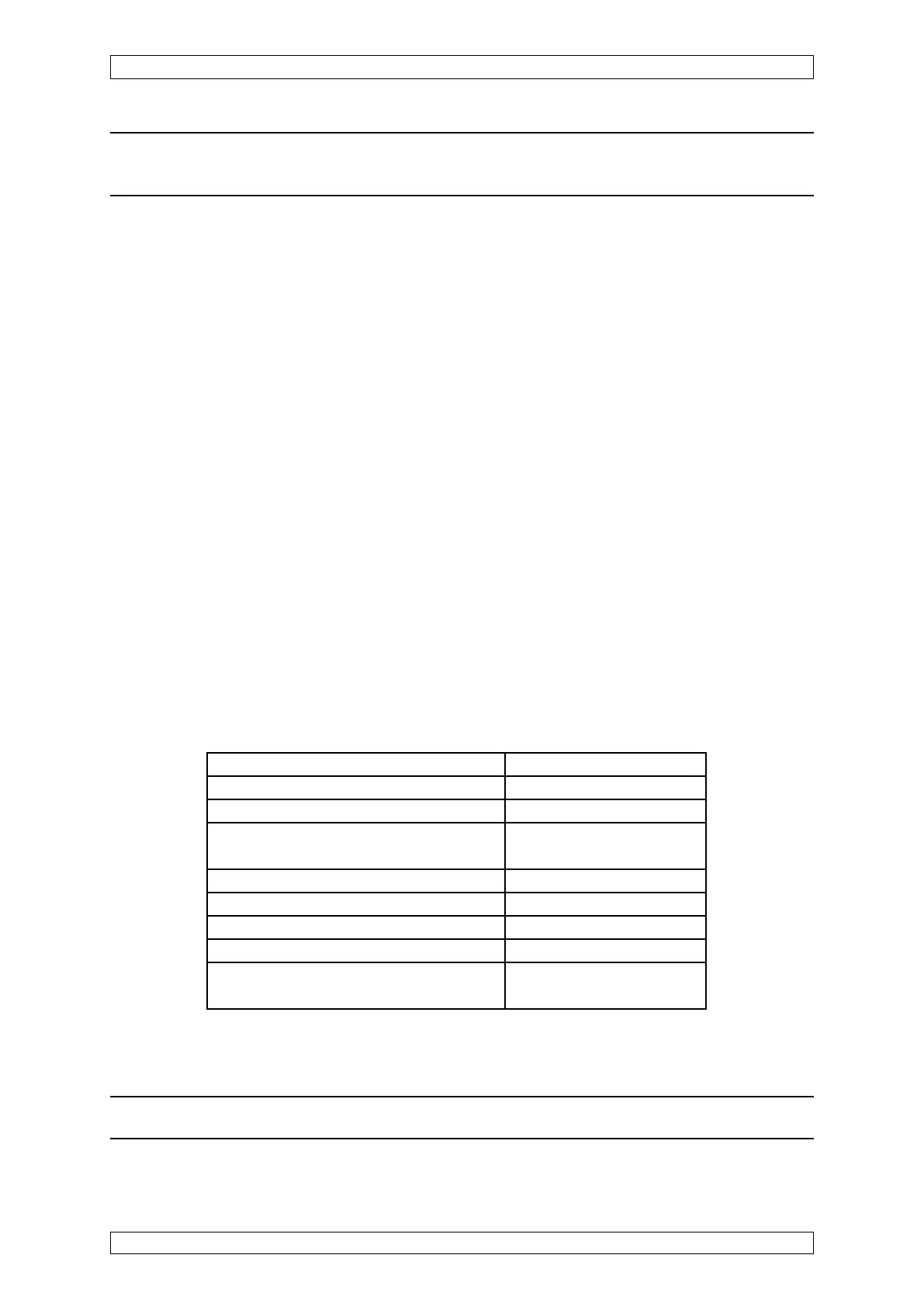
Module Conductor Cross Section
MAT-/MAT-TS-Module 0,2 mm
2
- 1,5 mm
2
MRO-8-/MRO-8-TS-/MRO-16-TS-Module 0,2 mm
2
- 2,5 mm
2
MRC-TS-Module
(Supply Voltage, Relay Lock) 0,2 mm
2
- 2,5 mm
2
MGT-40-TS-Module 0,2 mm
2
- 2,5 mm
2
MIB-Module (Supply Voltage) 0,2 mm
2
- 4,0 mm
2
MIB-Module (System Failure Relays) 0,2 mm
2
- 2,5 mm
2
MSP-Module (rack power supply, 150 W) 0,2 mm
2
- 4,0 mm
2
MST-Module (Alarm Reset, Horn Reset,
Relay Inhibit, Key Switch) 0,2 mm
2
- 2,5 mm
2
Table 5-1: Allowed Conductor Cross Sections
Note: Conductors must be copper and can be either stranded or solid.