REV 0, June 2005Page 112
Operation Manual SUPREMA
5. Installation
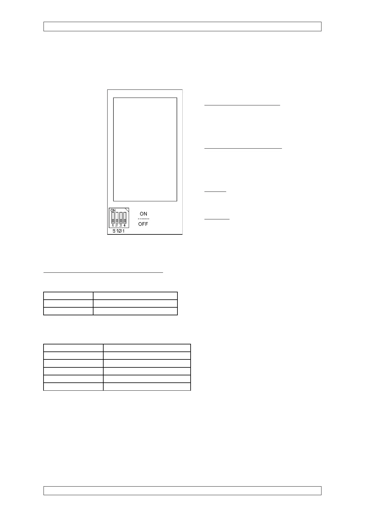
5.3.18 Configuration of the MFI Module*
S101 Code Switch
Functions S101
1 = ON, 2 = ON, 3 = OFF
The fire detectors are powered from
the SUPREMA power supply (no dc
decoupling between signal line and
SUPREMA power supply)
1 = OFF, 2 = OFF, 3 = ON
The fire detectors are powered from a
separate power supply. Signal line and
SUPREMA power supply are
electrically isolated.
4 = ON
The module is configured for
applications with a zener barrier.
4 = OFF
The module is configured for
applications without a zener barrier.
Figure 5-18: View of the MFI Module
Configuration in the SUPREMA menu
Settings/Measure points/Sensor data
Settings/Measure points/Alarms
1st alarm/level 30.00
Above alarm level Alarm
Below alarm level No alarm
Latching Alarm latching
2nd to 4th alarm de-activated
2nd to 4th level de-activated
Sensor MFI
Measuring range 0 ... 100
Units any
* With regard to fire and smoke detection, the SUPREMA has not been evaluated to any Canadian standard by a
third party agency.