REV 0, June 2005Page 194
Operation Manual SUPREMA
7. Maintenance and Service
7.2 Sensor Simulation Modules
For function test of the SUPREMA sensor inputs, simulation modules can be used independently
from the sensor type.
7.2.1 Description of Function of Sensor Simulation Module 4-20mA, WT, HL
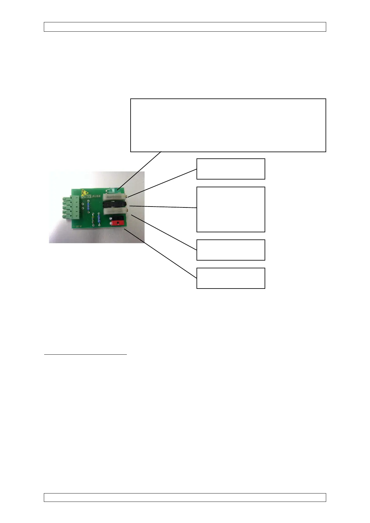
Design
Figure 7-1: Sensor simulation module
Setting and Operation
After plugging the sensor simulator into a MAT a desired measuring value is adjusted for operation
with zero signal by means of rotation at the zero signal potentiometer. By plugging the switch
another measuring value is simulated which is regulated by the span signal potentiometer. It
can be measured at both of the test jacks or directly at the MAI by means of a voltmeter.
Examples
for MCI – Check 4 ... 20 mA
Sensor type: DF-9500
Measuring gas: Carbon monoxide
Zero gas: Air
Reference gas: Carbon monoxide
U
a
at open switch (Normal operation): 400 mV
U
a
at closed switch (Alarm) : 1.9 V
The sensor simulation module may be used only to the check and presetting and not to the
calibration.
Signal-LED
green: Sensor simulation 4 ... 20 mA, Order No.: 10030262
red: Sensor simulation Catalytic Combustion Order No.: 10030263
yellow: Sensor simulation Semiconductor Order No.: 10030264
ZERO signal
potentiometer
Test Jacks
SPAN signal
potentiometer
Plug Switch
plugged = SPAN
pulled = ZERO