REV 0, June 2005Page 106
Operation Manual SUPREMA
5. Installation
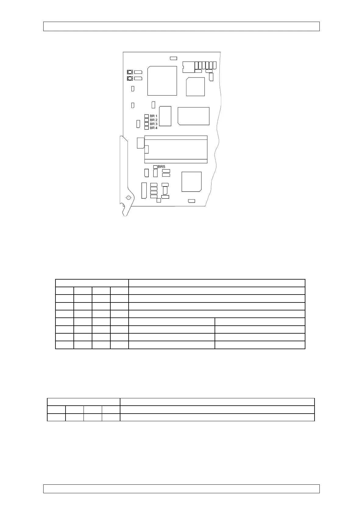
Figure 5-10: Configuration of the MAO module
As of layout version 6, the operating modes for CAN-A or CAN-B buses and the turn-on behaviour
must be configured with the S3 and S4 DIL switches.
FREE-A-/B settings
CAN-A-/B setting
Switch S3 Function
1234
OFF OFF ON ON Function FREE-A/B by switches on the MIB module
X X OFF OFF Function by switch FREE-A/B on the MAO PCB
Turn-on behaviour Behaviour at CAN failure
OFF OFF OFF OFF All analogue outputs at 2 mA. All analogue outputs at 2 mA.
X ON OFF OFF Last state is kept
ON X OFF OFF All analogue outputs at 0 mA.
X: Any switch
Switch S4 Function
1234
ON ON OFF OFF Control of the MAO PCB by CAN-A bus (also for redundant applications