REV 0, June 2005 Page 115
Operation Manual SUPREMA
5. Installation
5.3.20 MRD 10 Dummy Relay
Module application/function
Up to 5 relay modules can be connected (MRO10–8/MRO10–16) to the MRC module. If not all
5 relay modules are connected, an MRD module must be plugged into each of the unused
relay module connectors. The unused relays are simulated by this module.
With an MRD module connected the driver outputs of the MGO module are provided with a
fixed load. Monitoring the driver outputs therefore allows a failure state to be recognised.
All 40 outputs of the MGO10 modules are monitored. Output failures (open/short circuit) are
identified and are reported as a system failure.
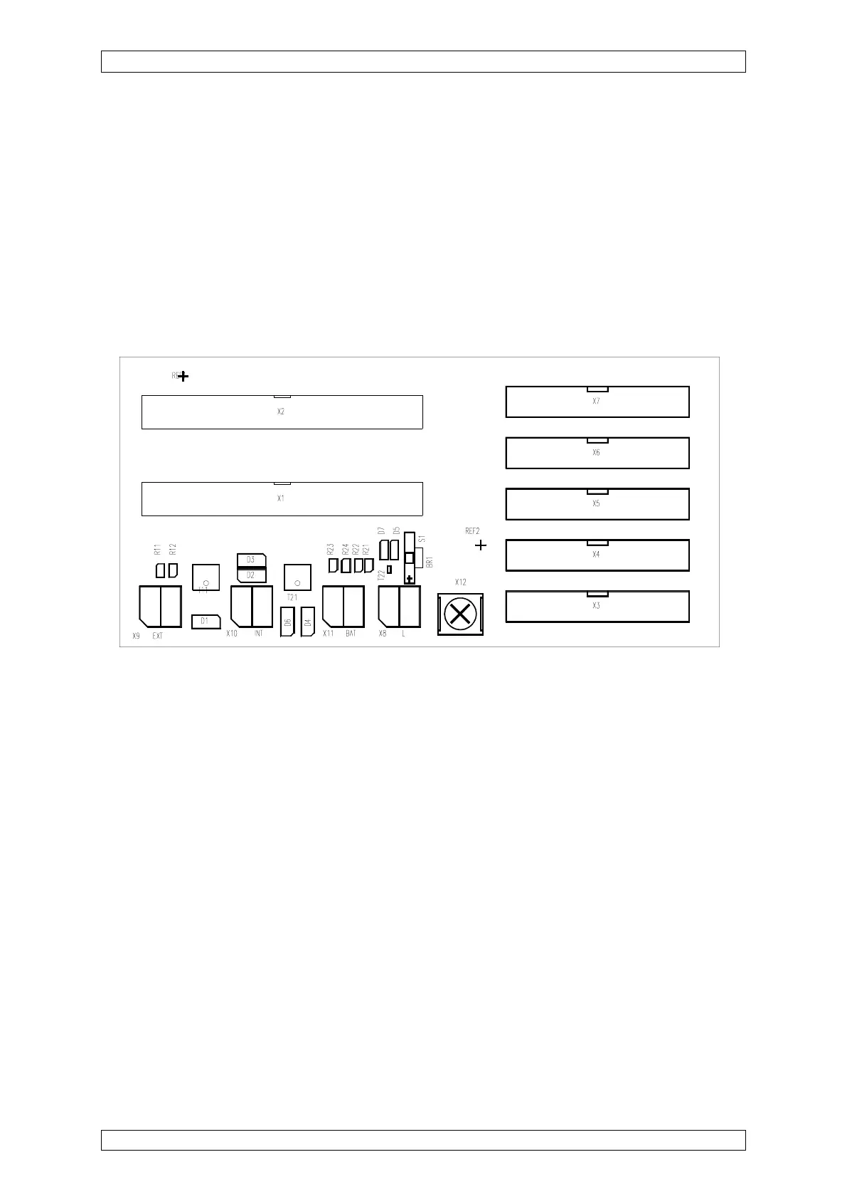
Figure 5-20: View of the MRC module
MRC10
X3 -X7 = 20-pin connection for relay modules MRO10–8/MRO10–16
Unused relay module connections have to be fitted with MRD modules.
Module use/connection
On each MRD module one resistor is connected in series with a light-emitting diode to provide
the load for the MGO module. The light-emitting diodes show the switching state of the MGO
driver output.
LED ON = driver output conducting = relay activated
LED OFF = driver output not conducting = relay deactivated