REV 0, June 2005 Page 97
Operation Manual SUPREMA
5. Installation
Explanation of the symbols:
= Any switch
Explanation of the symbols:
= Any switch
CAN-BUS Terminating Resistors
Both CAN bus systems (CAN-A + CAN-B) of the SUPREMA must have a terminating resistor at
each end of the bus. One end of the bus is located on the MDO module. A terminating resistor
is permanently connected here. For a 1-rack system, the other end of the bus is at the rear-
panel wiring of the MIB. If the system consists of only one rack, switches 1 and 2 of the DIL
switch must be set to the lower position.
If an additional rack is provided for the system, the racks are connected to each other at the
rear via the MST cards with ready-made CAN bus cables.
For a “multi-rack” system, the DIL switch contacts 1 and 2 (CAN-A, CAN-B) of the last rack – by
which the CAN BUS is ending - must be set to the lower position, all DIL switch contacts 1 and
2 (CAN-A, CAN-B) on the intermediate racks must be set to the upper position.
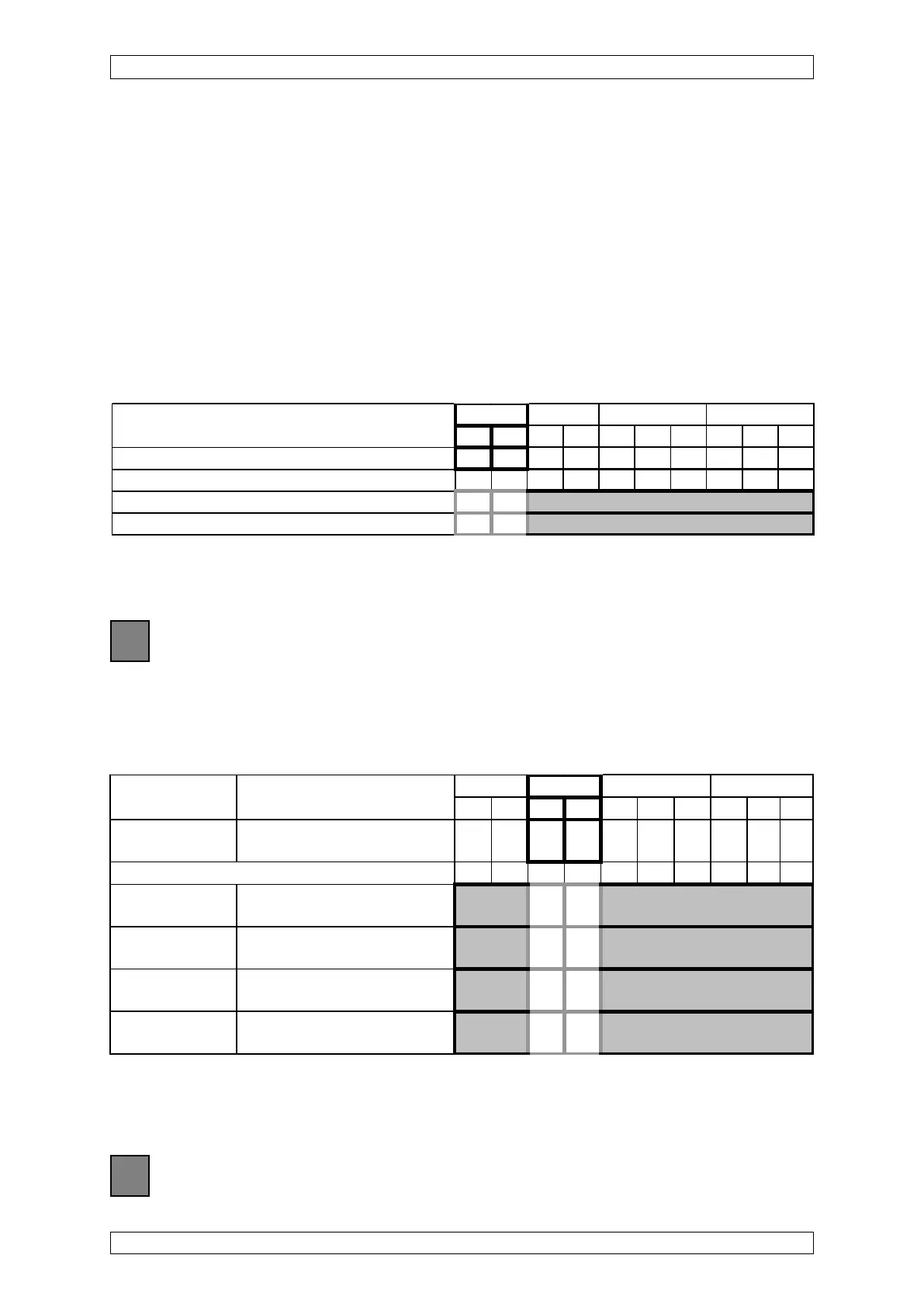
Table 5-6: CAN Bus Terminating Resistors
CAN FREE Baud
ABAB421421
Switch No. 12345678910
In the case of alternative assembly 10 9 8 7 6 5 4 3 2 1
Terminating Resistor Closed ON ON
Terminating Resistor Open OFF OFF
Turn-on Behaviour and Failure Behaviour of the MGO Module
Table 5-7: MGO Module, Configuration of turn-on behaviour and failure behaviour
CAN FREE Baud Rack
ABAB421421
Turn-on Behaviour at CAN-Bus 12345678910
behaviour failure
In the case of alternative assembly 10 9 8 7 6 5 4 3 2 1
All relays remain All relays keep their last state ON ON
de-energised (except for blinking).
All relays remain After 72 h, all relays are OFF ON
de-energised de-energised.
All relays are All relays keep their last state ON OFF
energised (except for blinking).
All relays are After 72 h, all relays are OFF OFF
energised energised.