REV 0, June 2005 Page 107
Operation Manual SUPREMA
5. Installation
Note: The MAO module is always controlled by the CAN-A bus and is always
outputting the measuring values of the MDO module.
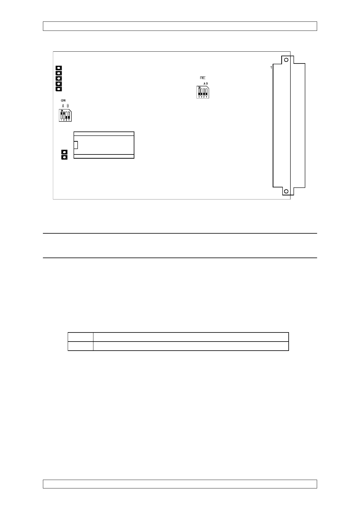
5.3.14 Configuration of the MGO Module
Plug-in bridges (BR1-BR4) can be used to select whether the MGO card is controlled via
the CAN-A or via the CAN-B bus.
Configuration of turn-on and failure behaviour of the MGO module is effected via the DIL
switch on the MIB module (FREE A + FREE B).
CAN-A BR11 + BR13 = CLOSED & BR12 + BR14 = OPEN (Standard Setting)
CAN-B BR11 + BR13 = OPEN & BR12 + BR14 = CLOSED
Figure 5-11: Configuration MAO module, Layout version 6