REV 0, June 2005Page 222
Operation Manual SUPREMA
10. Redundant Systems
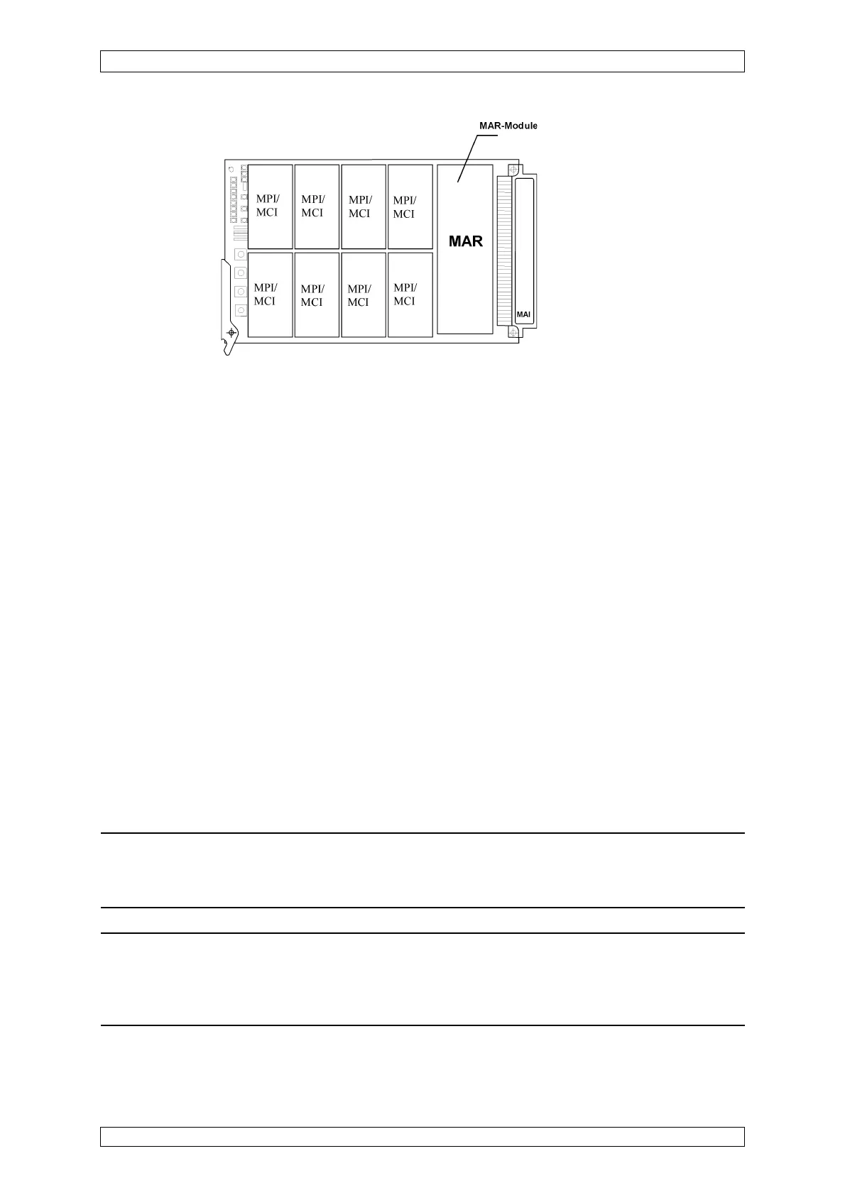
Figure 10-2: MAI Module with MAR Module
10.3.3 Installation of MCP and MDA Module
The second MCP module must be plugged into rack position Slot 2, and the second MDA
module into rack position Slot 5.
Before plugging the modules, the SUPREMA system must be voltage-free.
These modules are normally operated as CAN B, a hardware configuration is not necessary.
10.3.4 Output Drivers/Relay Ouputs
The MGO modules provide switching outputs (24V DC / 300 mA, short-circuit safe and overload
safe) for control of information and alarms (LEDs, relays, solenoid valves etc.). In redundant
systems, both channels must have the same number of MGO modules connected.
If relays are needed instead of the driver outputs, because a separation of potentials is required
or other voltages have to be switched, the relay modules MRO-8-TS or MRO-16-TS may be
used. Both modules are suitable for “G” or Top Hat type DIN rail mounting and provide 8 relay
ouputs per module in a compact design. The MRO-8-TS module has 1 changeover contact per
relay. Connection to the relay contacts is via screw terminals.
The use of MRO-16-TS modules permits the redundant lay out of the following wiring and
control of actuating and notice elements.
At use of MRO-8-TS modules only the non-redundant control of actuating and notice elements
is possible.
Attention: The lay-out of the circuit connected to the MRO-8-TS resp. MRO-16-TS
modules depends on the requirements of the respective application. It is completely
up to the user´s responsibility to observe the valid standards and guidelines.
Note: The MRO-16-TS Modules do not have changeover contacts. The working
contacts of the redundant relays are connected in series. (1 or 2 contacts open =
alarm). Two terminal blocks with screw terminals are used to connect to the relay
contacts.